Toyota Sienna Service Manual: Freeze frame data
1. DESCRIPTION
- The ECM records vehicle and driving condition information as freeze frame data the moment a DTC is stored. When troubleshooting, freeze frame data can be helpful in determining whether the vehicle was running or stopped, whether the engine was warmed up or not, whether the air-fuel ratio was lean or rich, as well as other data recorded at the time of a malfunction.
HINT: If it is impossible to duplicate the problem even though a DTC is detected, confirm the freeze frame data.
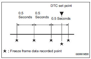
- The ECM records engine conditions in the form of freeze frame data every 0.5 seconds. Using the intelligent tester, five separate sets of freeze frame data, including the data values at the time when the DTC was set, can be checked.
- 3 data sets before the DTC was set
- 1 data set when the DTC was set
- 1 data set after the DTC was set
These data sets can be used to simulate the condition of the vehicle around the time of the occurrence of the malfunction. The data may assist in identifying of the cause of the malfunction, and in judging whether it was temporary or not.
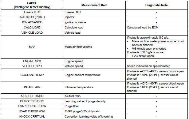
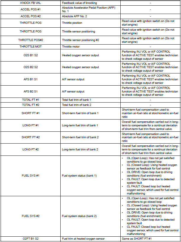
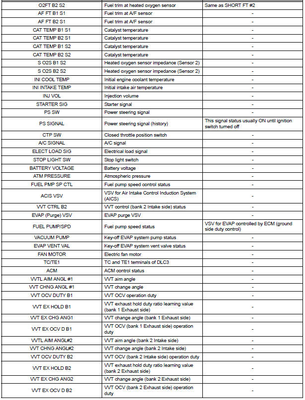
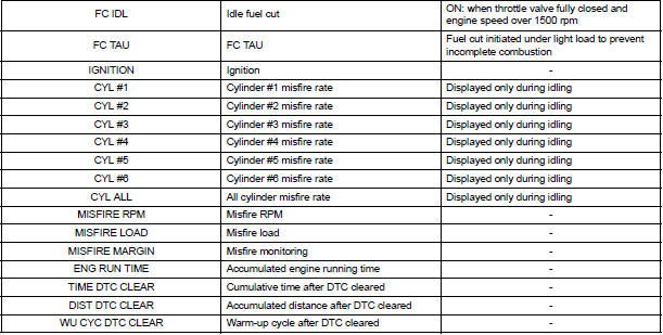
2. LIST OF FREEZE FRAME DATA
 DTC check / clear
NOTICE:
All the stored DTCs and freeze frame data are erased if:
the ECM is changed from normal mode to check mode
or vice versa; or 2) the ignition switch is turned from ON
to ACC or o ...
 Check mode procedure
HINT:
Intelligent tester only:
Compared to normal mode, check mode is more sensitive to
malfunctions. Therefore, check mode can detect the
malfunctions that cannot be detected by normal mode.
NOT ...
Other materials:
U151f automatic transaxle
Service data
TORQUE SPECIFICATIONS
...
Road test
1. PROBLEM SYMPTOM CONFIRMATION
Inspect the SET function.
Turn the cruise control main switch on.
Drive at the required speed between 40 km/h
(25 mph) and 200 km/h (125 mph).
Push the cruise control main switch to -
(COAST)/SET.
After releasing t ...
SRS airbags
The SRS airbags inflate when the vehicle is subjected to certain
types of severe impacts that may cause significant injury to the
occupants. They work together with the seat belts to help reduce
the risk of death or serious injury.
SRS front airbags
SRS driver airbag/front passenger ...
