Toyota Sienna Service Manual: Check mode procedure
HINT: Intelligent tester only: Compared to normal mode, check mode is more sensitive to malfunctions. Therefore, check mode can detect the malfunctions that cannot be detected by normal mode.
NOTICE: All the stored DTCs and freeze frame data are erased if:
- the ECM is changed from normal mode to check mode
or vice versa; or 2) the ignition switch is turned off or
turned to the ACC position from the ON position while in
check mode.
Before changing modes, always check and make a note of any DTCs and freeze frame data.
1. CHECK MODE PROCEDURE (Using an intelligent tester)
- Check and ensure the following conditions:
- Battery voltage 12 V or more
- Throttle valve fully closed
- The shift lever in the P or N position
- A/C switched OFF
- Turn the ignition switch off.
- Connect an intelligent tester to the DLC3.
- Turn the ignition switch to the ON position.
- Turn the tester ON.
- Select the following menu items: DIAGNOSIS / ENHANCED OBD II / CHECK MODE.
- Switch the ECM from normal mode to check mode.
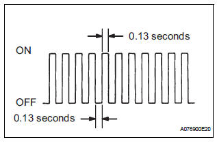
- Make sure that the MIL flashes as shown in the illustration.
- Start the engine.
- Make sure that the MIL goes off.
- Simulate the conditions of the malfunction described by the customer.
- Check for DTCs and freeze frame data using the tester.
 Freeze frame data
1. DESCRIPTION
The ECM records vehicle and driving condition
information as freeze frame data the moment a DTC
is stored. When troubleshooting, freeze frame data
can be helpful in dete ...
 Fail-safe chart
If any of the following DTCs are set, the ECM enters fail-safe
mode to allow the vehicle to be driven temporarily.
HINT:
*1: The vehicle can be driven slowly when the accelerator
ped ...
Other materials:
How to scroll
: Select to scroll to the next
or previous page.
: If
appears to the right of
titles, the complete titles are
too long for the display. Select
this button to scroll the title.
Turn the “TUNE•SCROLL” knob
to move the cursor box to select a
desired item from the list, and
press ...
Short to B+ in Side Squib LH Circuit
DTC B0118/46 Short to B+ in Side Squib LH Circuit
DESCRIPTION
The side squib LH circuit consists of the center airbag sensor assembly and
the front seat side airbag
assembly LH (side squib LH).
This circuit instructs the SRS to deploy when deployment conditions are met.
DTC B0118/46 is re ...
Warning light and indicator light bulb check
(a) Check the warning lights.
(1) Release parking brake pedal.
(2) When the ignition switch is turned to the ON
position, check that the ABS warning light,
BRAKE warning light, VSC warning light, TRAC
OFF indicator light (2WD) and SLIP indicator
light stay on for approx. 3 seconds.
HI ...
