Toyota Sienna Service Manual: Front axle hub bolt
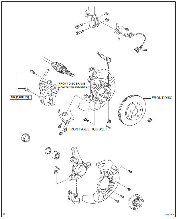
COMPONENTS
Replacement
HINT: Replace the RH side using the same procedures as for the LH side.
1. REMOVE FRONT WHEEL
2. SEPARATE FRONT DISC BRAKE CALIPER ASSEMBLY LH (See page AH-5)
3. REMOVE FRONT DISC
4. REMOVE FRONT AXLE LH HUB BOLT
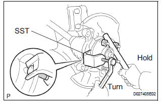
(a) Temporarily install the 2 nuts and washers to the front axle LH hub bolt as shown in the illustration.
(b) Using SST(s) and a screwdriver or an equivalent to hold the front axle, remove the front axle LH hub bolt.
SST 09628-10011
5. INSTALL FRONT AXLE LH HUB BOLT
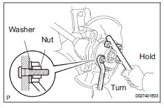
(a) Install a washer and nut to a new front axle LH hub bolt as shown in the illustration.
(b) Using a screwdriver to hold the front axle, install the hub bolt by torquing the nut.
6. INSTALL FRONT DISC
7. INSTALL FRONT DISC BRAKE CALIPER ASSEMBLY LH (See page AH-9)
8. INSTALL FRONT WHEEL Torque: 103 N*m (1,050 kgf*cm, 76 ft.*lbf)
 Axle system
PROBLEM SYMPTOMS TABLE
Use the table below to help you find the cause of the problem.
The numbers indicate the priority of the likely cause of
problem. Check each part in order. If necessary, rep ...
 Front axle hub
COMPONENTS
...
Other materials:
Camshaft Position Sensor "B" Circuit
DESCRIPTION
The exhaust camshaft's Variable Valve Timing (VVT) sensor consists of a
magnet and MRE (Magneto
Resistance Element).
The exhaust camshaft has a sensor plate with 3 teeth on its outer circumference.
When the exhaust camshaft rotates, changes occur in the air gaps between the ...
Power Slide Door RH does not Operate When Satellite Switch is
Pressed
DESCRIPTION
The power slide door operates only when the power slide door main
switch is ON (switch free: orange
paint on the top of the switch appears). The power slide door ECU RH
controls the power slide door
RH, which activates the slide door motor to open / close the slide do ...
Perform signal check
HINT:
When entering signal check mode, the tire pressure
warning ECU sets all the signal check DTCs first.
After completing signal check for each inspection
item, the DTCs for systems that are determined to be
normal by the tire pressure warning ECU will be
erased.
The DTCs f ...
