Toyota Sienna Service Manual: Camshaft Position Sensor "B" Circuit

DESCRIPTION
The exhaust camshaft's Variable Valve Timing (VVT) sensor consists of a magnet and MRE (Magneto Resistance Element).
The exhaust camshaft has a sensor plate with 3 teeth on its outer circumference.
When the exhaust camshaft rotates, changes occur in the air gaps between the 3 teeth and MRE, which affects the magnet. As a result, the resistance of the MRE material fluctuates. The VVT sensor converts the exhaust camshaft rotation data to pulse signals, uses the pulse signals to determine the camshaft angle, and sends it to the ECM.
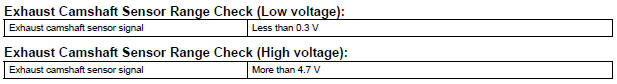
MONITOR DESCRIPTION
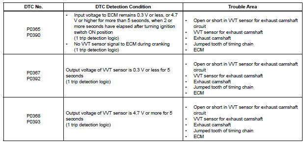
If no signal is transmitted by the VVT (for exhaust camshaft) sensor despite the engine revolving, or the rotations of the exhaust camshaft and the crankshaft are not synchronized, the ECM interprets this as a malfunction of the sensor.
MONITOR STRATEGY
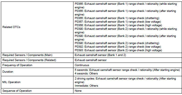
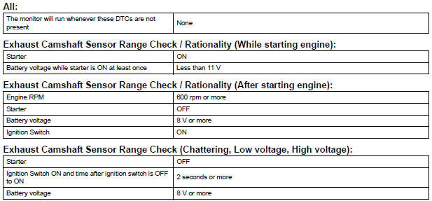
TYPICAL ENABLING CONDITIONS
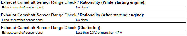
TYPICAL MALFUNCTION THRESHOLDS
WIRING DIAGRAM
Refer to DTC P0335 (See page ES-222).
INSPECTION PROCEDURE
HINT:
Read freeze frame data using the intelligent tester. The ECM records vehicle and driving condition information as freeze frame data the moment a DTC is stored. When troubleshooting, freeze frame data can be helpful in determining whether the vehicle was running or stopped, whether the engine was warmed up or not, whether the air-fuel ratio was lean or rich, as well as other data recorded at the time of a malfunction.
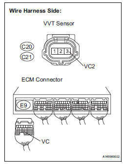
1 CHECK VVT SENSOR FOR EXHAUST CAMSHAFT (SENSOR POWER SOURCE)
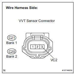
(a) Disconnect the C21 or C20 VVT sensor connector.
(b) Measure the voltage according to the value(s) in the table below.
Standard voltage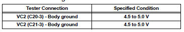


2 CHECK HARNESS AND CONNECTOR (VVT SENSOR - ECM)
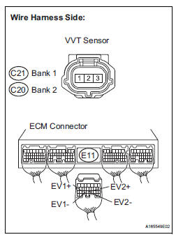
(a) Disconnect the C21 or C20 VVT sensor for exhaust camshaft connector.
(b) Disconnect the E11 ECM connector.
(c) Measure the resistance between the wire harness side connectors.
Standard resistance: 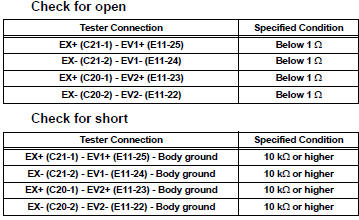

3 CHECK VVT SENSOR FOR EXHAUST CAMSHAFT (SENSOR INSTALLATION)
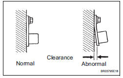
(a) Check the VVT sensor installation.
OK: Sensor is installed correctly.


4 CHECK EXHAUST CAMSHAFT
(a) Check the teeth of the camshaft.


5 REPLACE VVT SENSOR (FOR EXHAUST CAMSHAFT)
(a) Replace the VVT sensor (See page ES-509).

6 CHECK WHETHER DTC OUTPUT RECURS
(a) Connect the intelligent tester to the DLC3.
(b) Turn the ignition switch to the ON position.
(c) Turn the intelligent tester on.
(d) Clear the DTCs.
(e) Select the following menu items: DIAGNOSIS / ENHANCED OBD II / DTC / INFO / PENDING CODES.
(f) Read the DTCs.
Result 
HINT:
If the engine does not start, replace the ECM.


END
7 CHECK HARNESS AND CONNECTOR (VVT SENSOR - ECM)
(a) Disconnect the C18 or C19 VVT sensor connector.
(b) Disconnect the E9 ECM connector.
(c) Measure the resistance according to the value(s) in the table below.
Standard resistance : 
(d) Reconnect the VVT sensor connector.
(e) Reconnect the ECM connector.

REPLACE ECM (See page ES-498)
 Ignition Coil "A" Primary
HINT:
These DTCs indicate malfunctions relating to the primary circuit.
If DTC P0351 is set, check the No. 1 ignition coil with igniter circuit.
If DTC P0352 is set, check the No. 2 igniti ...
 Catalyst System Efficiency Below Threshold
MONITOR DESCRIPTION
The ECM uses the sensors mounted in front of and behind the three-way
catalyst (TWC) to monitor its
efficiency. The first sensor, an Air Fuel ratio (A/F) sensor, sends pre- ...
Other materials:
Removal
1. RECOVER REFRIGERANT FROM REFRIGERATION
SYSTEM (See page AC-172)
2. REMOVE NO. 2 AIR CLEANER INLET (See page EM-
28)
3. REMOVE FRONT BUMPER ASSEMBLY (See page
ET-3)
4. DISCONNECT DISCHARGE HOSE SUB-ASSEMBLY
(a) Remove the bolt and disconnect the discharge hose
sub-assembly from the coo ...
Installation
1. INSTALL THROTTLE BODY
Install a new throttle body gasket to the intake air
surge tank.
Install the throttle body with the 4 bolts.
Torque: 10 N*m (102 kgf*cm, 7 ft.*lbf)
Connect the 2 water by-pass hoses.
Connect the throttle body connector and clamp.
2. ...
Installation
1. INSTALL VANE PUMP ASSEMBLY
(a) Temporarily install the bolt to the vane pump
assembly.
(b) Install the vane pump assembly.
(c) Temporarily install the bolt (B).
(d) Using SST, tighten the 2 bolts.
SST 09249-63010
Torque:Without SST
43 N*m (439 kgf*cm, 32 ft.*lbf)
With SST
29 ...
