
Toyota Sienna Service Manual: Front wiper rubber
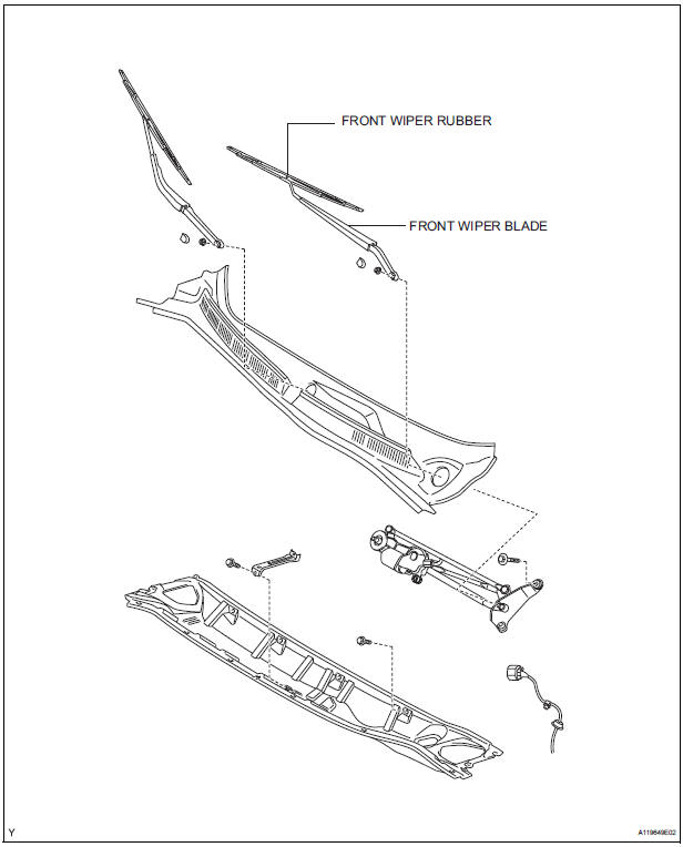
COMPONENTS
REMOVAL
1. REMOVE FRONT WIPER BLADE
- Remove the front wiper blade from the front wiper arm LH.
NOTICE: Do not fold down the front wiper arm with the front wiper blade being removed from it.
2. REMOVE FRONT WIPER RUBBER
- Remove the front wiper rubber from the front wiper blade.
- Remove the 2 wiper rubber backing plates from the front wiper rubber.
INSTALLATION
1. INSTALL FRONT WIPER RUBBER
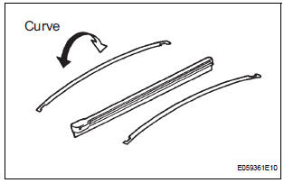
- Install the wiper rubber backing plates to the front wiper rubber.
NOTICE: Be careful about the right side and the wrong side of the backing plates.
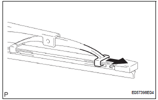
- Install the front wiper rubber so that the head part (Larger side) of the wiper rubber faces the arm axle side.
NOTICE: Push the front wiper blade into the grooves of the wiper rubber to engage them completely.
 Installation
1. INSTALL WINDSHIELD WIPER MOTOR ASSEMBLY
Apply MP grease to the crank arm pivot of the
windshield wiper motor assembly.
Install the windshield wiper motor assembly with the
...
 Rear wiper motor and bracket
COMPONENTS
REMOVAL
1. REMOVE REAR WIPER ARM
Remove the rear wiper arm head cap from the rear
wiper arm.
Remove the nut and the rear wiper arm.
2. REMOVE BACK DOOR GARN ...
Other materials:
Diagnosis system
1. CHECK DLC3
The vehicle's ECU uses ISO 15765-4 for
communication protocol. The terminal arrangement
of the DLC3 complies with SAE J1962 and matches
the ISO 15765-4 format.
NOTICE:
*: Before measuring the resistance, leave the
vehicle as is for at least 1 minute and do not
...
PCS (Pre-Collision
System)
When the radar sensor detects possibility of a frontal collision,
the pre-collision system such as the brakes and seat belts are
automatically engaged to lessen impact as well as vehicle damage.
Pre-collision warning
When a high possibility of a
frontal collision is detected, the
pre-colli ...
Receiving a call
When a call is received, the following screen is displayed
together with a sound.
To answer the phone
Press the switch on the steering
wheel or select .
To refuse a call
Press the switch on the steering
wheel or select
To adjust the incoming call volume
Turn the “PWR•VOL� knob ...
