Toyota Sienna Service Manual: Hood
COMPONENTS
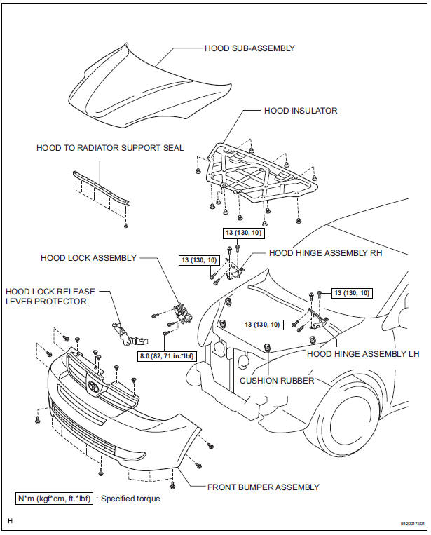
Adjustment
HINT: Since a centering bolt is used as a hood hinge mounting bolt and hood lock mounting bolt, the hood and hood lock can not be adjusted with them on. Substitute a bolt with a washer for the centering bolt.
1. INSPECT HOOD SUB-ASSEMBLY
- Check that the clearance is within the standard range.
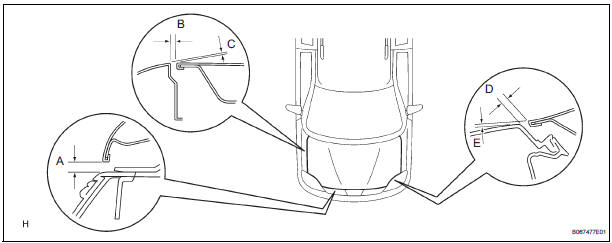
Standard

2. ADJUST HOOD SUB-ASSEMBLY
- Horizontally adjust the hood.
- Loosen the 4 hood hinge mounting bolts on the hood side.
- Adjust the clearance by moving the hood, so
that it will be in the standard range.
Standard (A): 4.0 +- 1.5 mm (0.157 +- 0.059 in.)
- Tighten the hood side hinge bolts after the
adjustment.
Torque: 13 N*m (130 kgf*cm, 10 ft.*lbf)
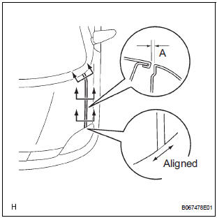
- Adjust the height of the hood front end using the cushion rubber.
- Adjust the cushion rubber so that the hood and the fender will be aligned.
HINT: The cushion rubber goes up and down when turned.
- Adjust the hood lock.
- Remove the front bumper cover (See page ET- 3).
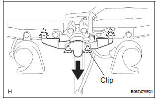
- Using a screwdriver, disengage the 4 claws and remove the hood lock release lever protector.
HINT: Tape the screwdriver tip before use.
NOTICE: Removing the protector damages the clips inside the protector. Therefore, the use of a new protector is necessary for installation.
- Loosen the 3 hood lock mounting bolts.
- Adjust the striker position by moving the hood lock, so that the striker can enter smoothly.
- Tighten the hood lock bolts after the
adjustment.
Torque: 8.0 N*m (82 kgf*cm, 71 in.*lbf)
 Power Back Door Warning Buzzer does not Sound
DESCRIPTION
The power back door system uses a warning buzzer built into the
back door, which has 3 ways of
sounding that are used differently according to the situations:
When all the f ...
 Front door
COMPONENTS
...
Other materials:
Terminals of ECU
1. RADIO AND NAVIGATION ASSEMBLY
*1: with Rear Seat Entertainment System
Reference: waveform 1
HINT:
Terminal: VV+ - VV-
Gauge set: 200 mV/DIV, 10 μs/DIV
Condition: DVD is played on radio and navigation
assembly
Reference: wave ...
Slide door lock
INSPECTION
1. INSPECT SLIDE DOOR LOCK REMOTE CONTROL SUB-ASSEMBLY LH
Inspect the resistance of the switch.
Resistance
If the result is not as specified, replace the control
assembly.
2. INSPECT SLIDE DOOR LOCK REMOTE CONTROL SUB-ASSEMBLY RH
Inspect the resistance of the swit ...
Receiving a message
When an e-mail/SMS/MMS is received, the incoming message screen
pops up with sound and is ready to be operated on the screen.
Select to check the message.
Select to refuse the message.
Select to call the message
sender.
Receiving a message
Depending on the cellular phone used f ...
