Toyota Sienna Service Manual: Precaution
1. GENERAL PRECAUTION
- When using the battery during inspection, do not bring the positive and negative tester probes too close to each other as a short circuit may occur.
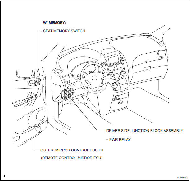
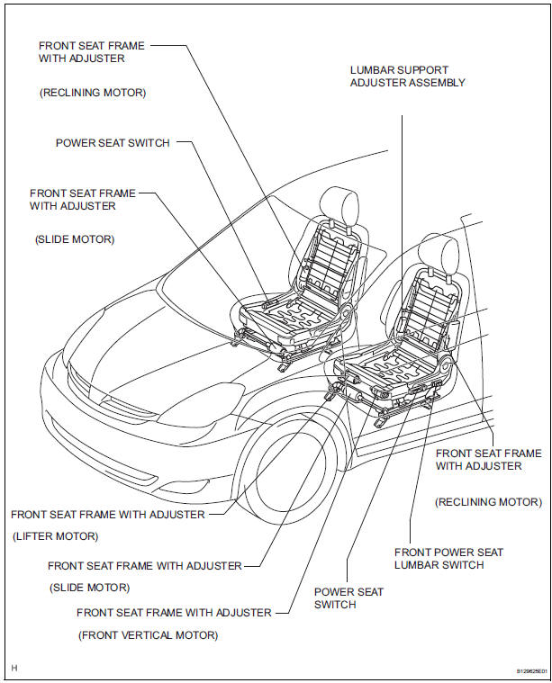
PARTS LOCATION
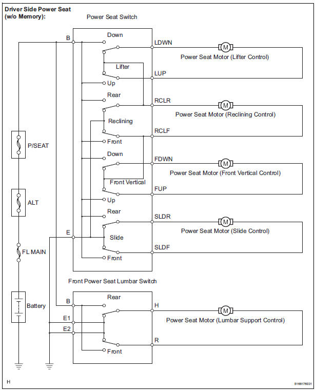
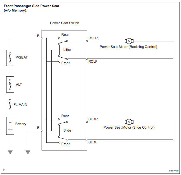
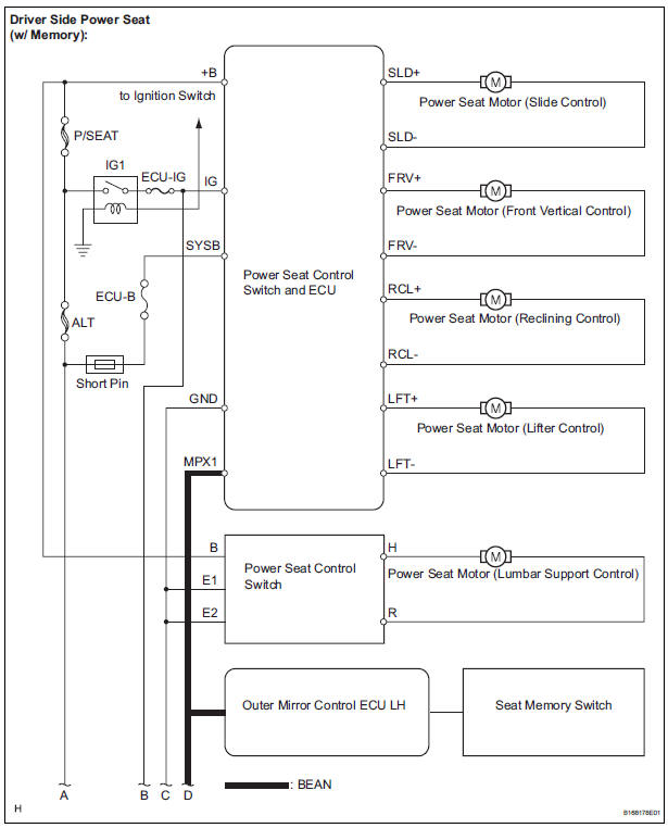
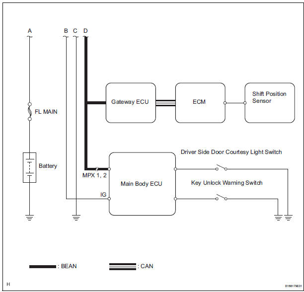
SYSTEM DIAGRAM
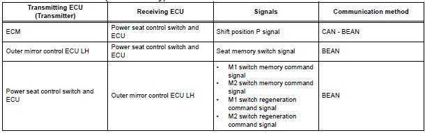
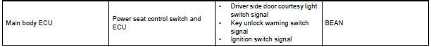
1. SIGNAL COMMUNICATION TABLE
Driver Side Power Seat (with Memory)

 System description
1. GENERAL DESCRIPTION
The power seat control system is equipped with the
following function:
The front seats are equipped with electric
adjuster slide, reclining, lifter, fr ...
Other materials:
Installation
1. INSTALL SHOCK ABSORBER ASSEMBLY REAR LH
(a) Install the rear spring bumper No.1 LH to the shock
absorber assembly LH.
(b) Support the rear axle beam assembly with a jack.
(c) Install the rear shock absorber assembly rear LH,
cushion retainer and nut to the rear axle beam.
(d) ...
Open in Stop Light Switch Circuit
DTC C1249/49 Open in Stop Light Switch Circuit
DESCRIPTION
This skid control ECU inputs the stop light switch signal and detects the
status of brake operation.
The skid control ECU has an open detection circuit. If an open in the stop light
switch input line or GND
side stop light circuit ...
On-vehicle inspection
1. INSPECT REAR AXLE HUB BEARING BACKLASH
(a) Using a dial gauge, check for backlash near the
center of the axle hub.
Maximum:
0.05 mm (0.0020 in.)
If backlash exceeds the maximum, replace the axle
hub assembly.
NOTICE:
Ensure that the dial gauge is set at right angles
to the measuremen ...
