Toyota Sienna Service Manual: How to proceed with troubleshooting
HINT: *: Use the intelligent tester.
1 VEHICLE BROUGHT TO WORKSHOP

2 CUSTOMER PROBLEM ANALYSIS
- (a) Confirm problem symptoms

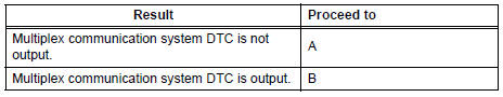
3 CHECK MULTIPLEX COMMUNICATION SYSTEM*
- Check if the multiplex communication system DTC is output.
HINT: The center airbag sensor assembly of this system is connected to the multiplex communication system.
Therefore, before starting troubleshooting, make sure to check that there is no trouble in the multiplex communication system.
Result:
 INSPECT MULTIPLEX
COMMUNICATION
CIRCUIT
INSPECT MULTIPLEX
COMMUNICATION
CIRCUIT

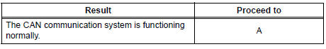
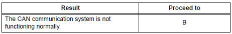
4 CHECK CAN COMMUNICATION SYSTEM*
- Use the intelligent tester to check if the CAN communication system is functioning normally .
HINT: The ECM is connected to the CAN communication system. Therefore, before starting troubleshooting, make sure to check that there is no trouble in the CAN communication system.
Result:
 INSPECT CAN COMMUNICATION
CIRCUIT
INSPECT CAN COMMUNICATION
CIRCUIT

5 SRS WARNING LIGHT CHECK
- Proceed to Diagnosis System

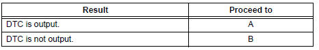
6 CHECK FOR DTC*
- Proceed to DTC Check / Clear (5).
Result:
 GO TO STEP 8

7 DIAGNOSTIC TROUBLE CODE CHART
- Proceed to Diagnostic Trouble Code Chart

GO TO STEP 10

8 SYMPTOM SIMULATION
- Proceed to Diagnosis System

9 PROBLEM SYMPTOMS TABLE
- Proceed to Problem Symptoms Table

10 CIRCUIT INSPECTION
11 IDENTIFICATION OF PROBLEM
12 REPAIR OR REPLACEMENT
13 CONFIRMATION TEST
END
 System description
1. GENERAL
In conjunction with impact absorbing structure for a
frontal collision, the SRS (Supplemental Restraint
System) driver airbag and front passenger airbag
were designed to supplemen ...
 Problem symptoms table
HINT:
Proceed to the troubleshooting for each circuit in the table
below.
AIRBAG SYSTEM
Symptom
Suspected Area
The SRS warning light goes off after the primary
check, ...
Other materials:
Crankshaft Position Sensor
DESCRIPTION
The Crankshaft Position (CKP) sensor system consists of a CKP sensor plate
and a pickup coil. The
sensor plate has 34 teeth and is installed on the crankshaft. The pickup coil is
made of an iron core and a
magnet.
The sensor plate rotates as each tooth passes through the pi ...
Stereo Component Amplifier Communication Error
INSPECTION PROCEDURE
1 IDENTIFY THE COMPONENT SHOWN BY THE SUB-CODE
Enter the diagnostic mode.
Press the preset switch "3" to change to "Detailed
Information Mode".
Identify the component shown by the sub-code.
HINT:
"190 (radio receiver ...
Short to GND in Front Passenger Side Squib
Circuit
DTC B0107/51 Short to GND in Front Passenger Side Squib
Circuit
DESCRIPTION
The front passenger side squib circuit consists of the center airbag sensor
assembly and the front
passenger airbag assembly.
The circuit instructs the SRS to deploy when deployment conditions are met.
DTC B0107/ ...
