Toyota Sienna Service Manual: System description
1. GENERAL
- In conjunction with impact absorbing structure for a frontal collision, the SRS (Supplemental Restraint System) driver airbag and front passenger airbag were designed to supplement seat belts in the event of a frontal collision in order to help reduce shock to the head and chest. This system is a 3-sensor type airbag system to detect the impact during a frontal collision using the center airbag sensor assembly and front airbag sensors. It also operates the airbag system and seat belt pretensioner.
- In order to detect the extent of the collision during the initial stages of the collision in further detail, the front airbag sensors have been changed from mechanical type to electrical type deceleration sensors. Accordingly, the deployment of the driver airbag and front passenger airbag is controlled in two stages according to the severity of the impact.
- In conjunction with impact absorbing structure for a side collision, the front seat side airbag and curtain shield airbag were designed to help reduce shock to the driver, front passenger, and rear outer passengers in the event of a side collision or rollover.
- RSCA (Roll Sensing of Curtain Shield Airbags) is used in order to deploy the curtain shield airbags and the seat belt pretensioner for the driver and front passenger, in the event that the vehicle rolls over.
- The curtain shield airbag that helps reduce shock to the front and rear seat occupants with a single curtain shield airbag has been adopted. In conjunction with this system, the side airbag sensors have been installed at the bottom of the center pillars and the rear airbag sensors have been installed at the bottom of the rear pillars respectively.
- In this system, a front side collision is detected by the side airbag sensors in order to deploy the front seat side airbag and curtain shield airbag. A rear side collision is detected by the rear airbag sensors and the center airbag sensor assembly in order to deploy the curtain shield airbag.
- The center airbag sensor assembly sends the airbag deployment signal to the ECM through BEAN (Body Electronics Area Network) and CAN (Controller Area Network) to operate the fuel pump control.
- The center airbag sensor assembly sends the airbag deployment signal to the body ECU via a discrete line to operate collision door lock release control.
2. CONSTRUCTION AND OPERATION
- FRONT AIRBAG SENSOR
- The front airbag sensors are installed on the right and left radiator supports respectively.
- The front airbag sensor uses an electrical type deceleration sensor.
- The deceleration sensor is built into the front airbag sensor, and the distortion that is created in the sensor is converted into an electric signal based on the vehicle deceleration rate during a frontal collision. Accordingly, the extent of the initial collision can be detected in detail.
- SIDE AIRBAG SENSOR
- The side airbag sensors are installed on the bottom of the right and left center pillars respectively.
- The side airbag sensor uses an electrical type deceleration sensor.
- The deceleration sensor is built into the side airbag sensor, and the distortion that is created in the sensor is converted into an electric signal based on the vehicle deceleration rate during a front side collision. Accordingly, the extent of the initial collision can be detected in detail.
- REAR AIRBAG SENSOR
- The rear airbag sensors are installed on the right and left rear pillars respectively.
- The rear airbag sensor uses an electrical type deceleration sensor.
- The deceleration sensor is built into the rear airbag sensor, and the distortion that is created in the sensor is converted into an electric signal based on the vehicle deceleration rate during a rear side collision. Accordingly, the extent of the initial collision can be detected in detail.
- CENTER AIRBAG SENSOR ASSEMBLY
- General
- The center airbag sensor assembly is installed on the center floor under the instrument panel.
- The center airbag sensor assembly consists of the deceleration sensor, safing sensor, ignition control circuit and diagnostic circuit.
- The center airbag sensor assembly receives signals from the deceleration sensor and safing sensor built into the center airbag sensor assembly and front airbag sensor and determines whether or not the driver airbag, front passenger airbag, and front seat belt pretensioners should be activated, and diagnoses system malfunctions.
- The center airbag sensor assembly receives signals from the deceleration sensor and the safing sensor built into the center airbag sensor assembly and the side airbag sensor and the rear airbag sensor, and determines whether or not the front seat side airbag and curtain shield airbag assemblies should be activated, and diagnoses system malfunctions.
- The center airbag sensor assembly sends the airbag deployment signal to the ECM through BEAN and CAN to operate fuel pump control.
- The center airbag sensor assembly sends the airbag deployment signal to the main body ECU through a discrete line to operate collision door lock release control.
- Deceleration sensor and ignition control circuit
- The deceleration sensor is built into the center airbag sensor assembly, front airbag sensor, side airbag sensor and rear airbag sensor, and the distortion created based on the deceleration of the vehicle during a frontal, front side or rear side collision is converted into an electric signal.
- The ignition control circuit performs calculations based on the signal output from the deceleration sensors of the center airbag sensor assembly, front airbag sensor, side airbag sensor and rear airbag sensor. If the calculated values are greater than the specified values, it activates an ignition operation.
- Safing sensor
- The safing sensor is built into the center airbag sensor assembly. During a frontal collision, the sensor turns on and outputs an ON signal to the center airbag sensor assembly if a deceleration rate greater than the specified value is applied to the safing sensor.
- Backup power source
- The backup power source consists of a power supply capacitor and a DC-DC converter. If the power system does not function during a collision, the power supply capacitor discharges and supplies electric power to the system. The DC-DC converter operates as a boosting transformer when the battery voltage falls below a predetermined level.
- Diagnostic circuit
- This circuit constantly diagnoses system malfunctions. When a malfunction is detected, it lights up the SRS warning light on the combination meter assembly to inform the driver.
- Memory circuit
- When a malfunction is detected in the diagnostic circuit, it is coded and stored in the memory circuit.
- SRS WARNING LIGHT
- The SRS warning light is located on the combination meter assembly. It comes on to inform the driver of system trouble when a malfunction is detected in self-diagnosis of the center airbag sensor assembly. Under normal operating conditions, when the ignition switch is turned to the ON position, it comes on for approximately 6 seconds and then goes off.
3. DEPLOYMENT CONDITION
When the vehicle collides and the shock is greater than the specified value, the SRS is activated automatically.
The center airbag sensor assembly includes the safing sensor and deceleration sensor. The safing sensor was designed to be turned on at a smaller deceleration rate than the deceleration sensor.
- The center airbag sensor assembly determines whether or not ignition is necessary based on signals from the deceleration sensor and the front airbag sensor (*1). If the safing sensor and deceleration sensor turn on simultaneously, current flows to the squibs to deploy the SRS as shown in the illustration below.
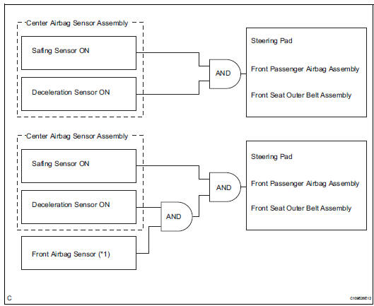
HINT: *1: In case of a front collision, the ignition signal could be output with the deceleration sensor ON signal even without a signal from the front airbag sensor.
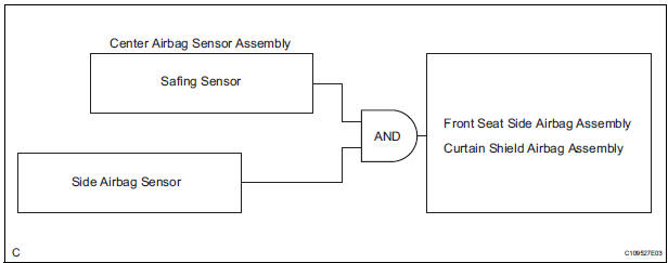
- The center airbag sensor assembly determines whether or not ignition is necessary based on signals from the side airbag sensor. If the safing sensor and side airbag sensor turn on simultaneously, current flows to the squib to deploy the SRS as shown in the illustration below.
- The center airbag sensor assembly determines whether or not ignition is necessary based on signals from the rear airbag sensor. If the safing sensor and rear airbag sensor turn on simultaneously, current flows to the squib to deploy the SRS as shown in the illustration below (*1).
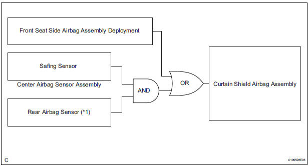
HINT: *1: If the front seat side airbag assembly deploys, the curtain shield airbag assembly will also deploy, regardless of whether the signal is output from the rear airbag sensor.
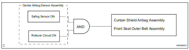
- The vehicle is equipped with the function to activate the SRS in case of vehicle rollover. A circuit to detect vehicle rollover is built into the center airbag sensor assembly. When the conditions for vehicle rollover are met, the SRS is activated as shown in the illustration below.
 Parts location
System diagram
...
 How to proceed with
troubleshooting
How to proceed with
troubleshooting
HINT:
*: Use the intelligent tester.
1 VEHICLE BROUGHT TO WORKSHOP
2 CUSTOMER PROBLEM ANALYSIS
(a) Confirm problem symptoms
3 CHECK MULTIPLEX COMMUNICATION SYSTEM*
Check if the multi ...
Other materials:
Camshaft Position "B" Actuator Circuit
DESCRIPTION
The Variable Valve Timing (VVT) system includes the ECM, OCV and VVT
controller. The ECM sends a
target duty-cycle control signal to the OCV. This control signal regulates the
oil pressure supplied to the
VVT controller. Camshaft timing control is performed according to engine ...
Removal
1. REMOVE CENTER REAR SEAT LAP TYPE BELT
ASSEMBLY (for 8-Passenger)
HINT:
Refer to the instructions for disassembly of the rear No. 1 seat assembly (for
center seat).
Remove the bolt and center seat lap type belt
assembly.
2. REMOVE CENTER REAR NO. 2 SEAT LAP BELT
ASSEMBLY WITH ...
Check for intermittent problems
1. CHECK FOR INTERMITTENT PROBLEMS
HINT:
For use of the intelligent tester only:
Inspect the vehicle's ECM using check mode.
Intermittent problems are easier to detect with an
intelligent tester when the ECM is in check mode. In
check mode, the ECM uses 1 trip detection logic, which
is more ...
