Toyota Sienna Service Manual: Idle Control System Malfunction
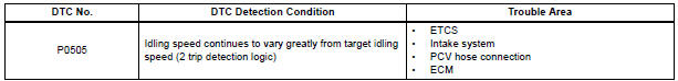
DTC P0505 Idle Control System Malfunction
DESCRIPTION
The idling speed is controlled by the ETCS (Electronic Throttle Control System). The ETCS is comprised of: 1) the one valve type throttle body; 2) the throttle actuator, which operates the throttle valve; 3) the Throttle Position (TP) sensor, which detects the opening angle of the throttle valve; 4) the Accelerator Pedal Position (APP) sensor, which detects the accelerator pedal position; and 5) the ECM, which controls the ETCS.
Based on the target idling speed, the ECM controls the throttle actuator to provide the proper throttle valve opening angle.
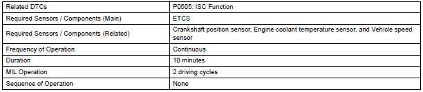
MONITOR DESCRIPTION
The ECM monitors the idling speed and idling air flow volume to conduct Idle Speed Control (ISC). The ECM determines that the ISC system is malfunctioning if the following conditions are met:
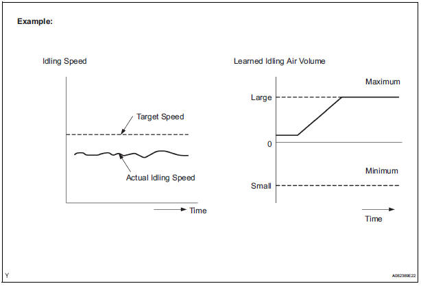
- The learned idling air flow volume remains at the maximum or minimum volume 5 times or more in a drive cycle.
- While driving at 6 mph (10 km/h) or more, the actual engine idling speed varies from the target idling speed by between 100 rpm and 200 rpm, 5 times or more in a drive cycle.
Example: If the actual idling speed varies from the target idling speed by more than 200 rpm* 5 times in a drive cycle, the ECM illuminates the MIL and sets the DTC.
*: Threshold idling speed varies according to the engine load.
MONITOR STRATEGY
TYPICAL ENABLING CONDITIONS

TYPICAL MALFUNCTION THRESHOLDS

INSPECTION PROCEDURE
HINT:
- The following conditions may also cause DTC P0505 to be set:
(a)The floor carpet overlapping slightly onto the accelerator pedal, causing
the accelerator pedal to be
slightly depressed and therefore the throttle valve position to be slightly
open.
(b)The accelerator pedal being not fully released.
- Read freeze frame data using the intelligent tester. The ECM records vehicle and driving condition information as freeze frame data the moment a DTC is stored. When troubleshooting, freeze frame data can be helpful in determining whether the vehicle was running or stopped, whether the engine was warmed up or not, whether the air-fuel ratio was lean or rich, as well as other data recorded at the time of a malfunction.
1 CHECK ANY OTHER DTCS OUTPUT (IN ADDITION TO DTC P0505)
- Connect the intelligent tester to the DLC3.
- Turn the ignition switch to the ON position.
- Turn the tester on.
- Select the following menu items: DIAGNOSIS / ENHANCED OBD II / DTC INFO / CURRENT CODES.
- Read the DTCs.
Result

HINT: If any DTCs other than P0505 are output, troubleshoot those DTCs first.
2 CHECK PCV HOSE CONNECTIONS
OK: PCV hose is connected correctly and is not damaged.
3 CHECK INTAKE SYSTEM
- Check the intake system for vacuum leakage.
OK: No leakage from intake system.
4 CHECK THROTTLE VALVE
- Check the throttle valve condition.
OK: No foreign objects between the throttle valve and housing.
REPLACE ECM
 Brake Switch
DTC P0504 Brake Switch "A" / "B" Correlation
DTC P0724 Brake Switch "B" Circuit High
DESCRIPTION
The stop light switch is a duplex system that transmits two signals: S ...
 Cold Start Idle Air Control System Performance
DTC P050A Cold Start Idle Air Control System Performance
DESCRIPTION
This monitor will run when the engine is started at -10 to 50C (14 to 122F)
of the engine coolant
temperature. The DTC will se ...
Other materials:
Sensor signal check by test mode (signal check) (when using sst check wire)
(a) When having replaced the skid control ECU and/or
yaw rate and deceleration sensor, perform zero
point calibration of the yaw rate and deceleration
sensor.
HINT:
If the ignition switch is turned from the ON
position to the ACC or off during test mode
(signal check), DTCs of the signal ...
Installation
1. INSTALL ENGINE OIL COOLER
(a) Clean the oil cooler contact surface on the cooler
mounting.
(b) Install a new O-ring to the oil cooler.
(c) Install the oil cooler assembly with the union bolt.
Torque: 68 N*m (693 kgf*cm, 50 ft.*lbf)
Install the 2 water by-pass hoses with the bolt ...
Removal
1. Remove rear wheel
2. Remove exhaust pipe assembly
Hint:
(see page ex-8)
3. Remove propeller with center bearing
shaft assembly
Hint:
(see page pr-3)
4. REMOVE REAR DIFFERENTIAL FILLER PLUG
(A) using a hexagon wrench (10 mm), remove the filler
plug and gasket.
5. Remove rear differentia ...
