Toyota Sienna Service Manual: Brake Switch
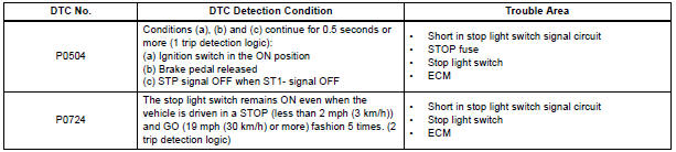
DTC P0504 Brake Switch "A" / "B" Correlation
DTC P0724 Brake Switch "B" Circuit High
DESCRIPTION
The stop light switch is a duplex system that transmits two signals: STP and ST1-. These two signals are used by the ECM to monitor whether or not the brake system is working properly. If the signals, which indicate the brake pedal is being depressed or released, are detected simultaneously, the ECM interprets this as a malfunction in the stop light switch and sets the DTC.
HINT: The normal conditions are as shown in the table below. The signals can be read using the intelligent tester.

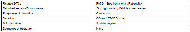
MONITOR DESCRIPTION
This DTC indicates that the stop light switch remains on. When the stop light switch remains ON during "stop and go" driving, the ECM interprets this as a fault in the stop light switch and the MIL comes on and the ECM stores the DTC. The vehicle must stop (less than 2 mph (3 km/h)) and go (19 mph (30 km/h) or more) 5 times for two driving cycles in order to detect a malfunction.
MONITOR STRATEGY
TYPICAL ENABLING CONDITIONS
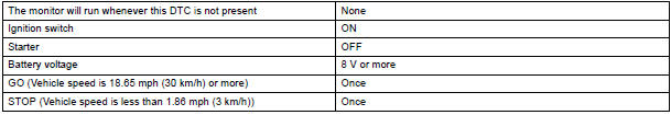
TYPICAL MALFUNCTION THRESHOLDS

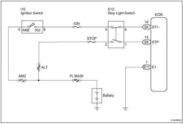
WIRING DIAGRAM
INSPECTION PROCEDURE
HINT: Read freeze frame data using the intelligent tester. The ECM records vehicle and driving condition information as freeze frame data the moment a DTC is stored. When troubleshooting, freeze frame data can be helpful in determining whether the vehicle was running or stopped, whether the engine was warmed up or not, whether the air-fuel ratio was lean or rich, as well as other data recorded at the time of a malfunction.
1 CHECK OPERATION OF STOP LIGHT
- Check whether the stop lights turn on and off normally when the brake pedal is depressed and released.
OK: Stop lights turn on when brake pedal is depressed.
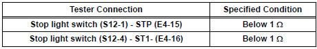
2 INSPECT STOP LIGHT SWITCH ASSEMBLY
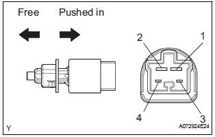
- Remove the S12 stop light switch assembly.
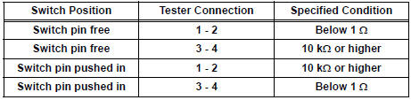
- Measure the resistance according to the value(s) in the table below.
Standard resistance
- Reinstall the stop light switch assembly.
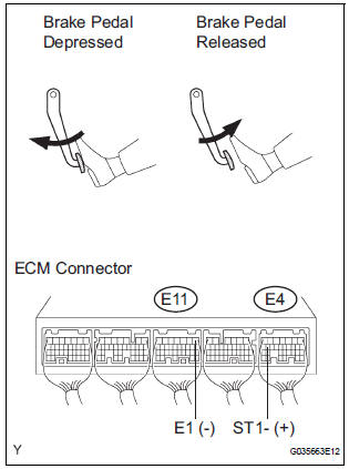
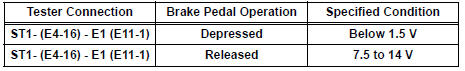
3 READ VALUE OF INTELLIGENT TESTER (STP SIGNAL AND ST1 - VOLTAGE)
- Connect the intelligent tester to the DLC3.
- Turn the ignition switch to the ON position and turn the tester on.
- Select the following menu items: DIAGNOSIS / ENHANCED OBD II / DATA LIST / PRIMARY / STOP LIGHT SW.
- Check the STP signal when the brake pedal is depressed and released.
Standard
- Measure the voltage according to the value(s) in the table below.
Standard voltage
4 CHECK HARNESS AND CONNECTOR (STOP LIGHT SWITCH - ECM)
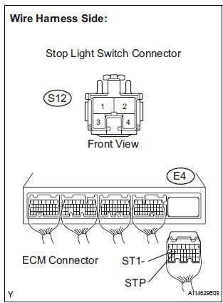
- Disconnect the S12 stop light switch connector.
- Disconnect the E4 ECM connector.
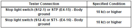
- Measure the resistance according to the value(s) in the table below.
Standard resistance : Check for open
Check for short
- Reconnect the stop light switch connector.
- Reconnect the ECM connector.
REPLACE ECM
 Vehicle Speed Sensor "A"
DTC P0500 Vehicle Speed Sensor "A"
DESCRIPTION
The speed sensor detects the wheel speed and sends the appropriate signals to
the skid control ECU.
The skid control ECU converts these ...
 Idle Control System Malfunction
DTC P0505 Idle Control System Malfunction
DESCRIPTION
The idling speed is controlled by the ETCS (Electronic Throttle Control
System). The ETCS is comprised
of: 1) the one valve type throttle bod ...
Other materials:
Side Airbag Sensor Assembly RH Circuit Malfunction
DTC B1140/32 Side Airbag Sensor Assembly RH Circuit Malfunction
DESCRIPTION
The side airbag sensor RH circuit consists of the center airbag sensor
assembly and side airbag sensor
RH.
If the center airbag sensor assembly receives signals from the side airbag
sensor RH, it judges whether or
...
Indicator Circuit
DESCRIPTION
The indicator displays the location of the obstacle and the approximate
distance between the vehicle and
the obstacle either by blinking or turning on.
WIRING DIAGRAM
INSPECTION PROCEDURE
1 CHECK HARNESS AND CONNECTOR (CLEARANCE WARNING ECU - AIR CONDITIONER
AMPLIFIER)
...
Removal
1. REMOVE FRONT DOOR LOWER FRAME BRACKET GARNISH LH
2. REMOVE FRONT DOOR INSIDE HANDLE BEZEL PLUG LH
3. REMOVE POWER WINDOW REGULATOR MASTER SWITCH ASSEMBLY
4. REMOVE FRONT DOOR TRIM BOARD SUBASSEMBLY LH
5. REMOVE SEAT MEMORY SWITCH
Disengage the 4 claws and remove the seat
memor ...
