Toyota Sienna Service Manual: Installation
1. INSTALL SHOCK ABSORBER ASSEMBLY REAR LH
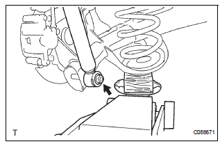
(a) Install the rear spring bumper No.1 LH to the shock absorber assembly LH.
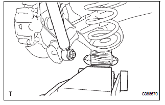
(b) Support the rear axle beam assembly with a jack.
(c) Install the rear shock absorber assembly rear LH, cushion retainer and nut to the rear axle beam.
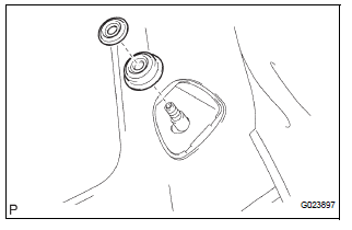
(d) Install the rear shock absorber cushion No.1 and rear shock absorber LH cushion retainer.
(e) Temporary tighten a new lock nut.
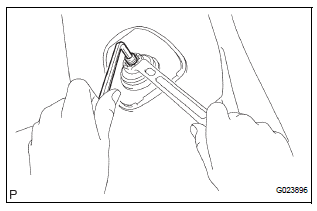
(f) Using a 6mm hexagon wrench to hold the piston rod, fully tighten the lock nut.
Torque: 30 N*m (310 kgf*cm, 22 ft.*lbf)
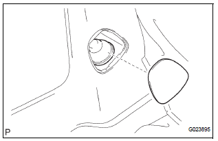
2. INSTALL REAR SHOCK ABSORBER CAP LH
(a) Install the shock absorber cap LH as shown in the illustration.
(b) Install the shock absorber head cover.
3. INSTALL REAR WHEEL
Torque: 103 N*m (1,050 kgf*cm, 76 ft.*lbf)
4. FULLY TIGHTEN SHOCK ABSORBER ASSEMBLY REAR LH
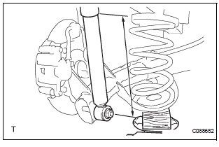
(a) Stabilize the shock absorber assembly rear LH.
If it is impossible to tighten the nut at this position, support the rear axle beam with a jack and load the rear compartment with a mass of approximately 90 kg (198 lb).
Length of shock absorber: 2WD DRIVE TYPE: 234 mm (9.22 in.) 4WD DRIVE TYPE: 258 mm (10.16 in.)
(b) Fully tighten the nut.
Torque: 115 N*m (1,173 kgf*cm, 85 ft.*lbf)
5. INSPECT REAR WHEEL ALIGNMENT
HINT: (See page SP-9)
 Inspection
1. INSPECT SHOCK ABSORBER ASSEMBLY REAR LH
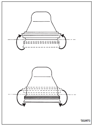
(a) Push down and pull up the shock absorber rod, and
check that there is no unusual resistance or unusual
operation sound.
If there is any malfunc ...
 Disposal
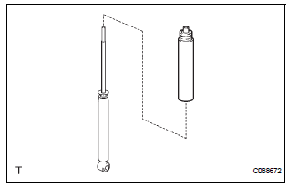
1. DISPOSE OF SHOCK ABSORBER ASSEMBLY REAR LH
(a) Fully extend the shock absorber rod.
(b) Using a drill, make a hole in the cylinder as shown in
the illustration to discharge the gas inside ...
Other materials:
Precaution
NOTICE:
When the ignition switch is turned off and the engine
temperature is high, the cooling fans may operate for
approximately 3 minutes.
After turning the ignition switch off, keep hands and
objects away from the fans when they are operating.
HINT:
If al ...
Short in Front Pretensioner Squib RH Circuit
DTC B0130/63 Short in Front Pretensioner Squib RH Circuit
DESCRIPTION
The front pretensioner squib RH circuit consists of the center airbag sensor
assembly and the front seat
outer belt assembly RH.
This circuit instructs the SRS to deploy when deployment conditions are met.
DTC B0130/63 ...
How to proceed with
troubleshooting
HINT:
Use these procedures to troubleshoot the power door lock
control system.
The intelligent tester should be used in steps 4 and 5.
1 VEHICLE BROUGHT TO WORKSHOP
2 CUSTOMER PROBLEM ANALYSIS CHECK
HINT:
In troubleshooting, confirm that the problem symptoms
have ...
