Toyota Sienna Service Manual: Installation
1. INSTALL TIRE PRESSURE WARNING RECEIVER ASSEMBLY
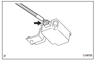
(a) Connect the connector.
(b) Install the tire pressure warning receiver assembly with the bolt.
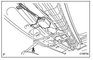
Torque: 5.0 N*m (51 kgf*cm, 44 in.*lbf)
2. INSTALL ROOF HEADLINING ASSEMBLY
HINT: Refer to the instructions for INSTALLATION of the ROOF HEADLINING (See page IR-14).
3. CONNECT CABLE TO NEGATIVE BATTERY TERMINAL
4. INSPECT TIRE PRESSURE WARNING SYSTEM
HINT: See page TW-25.
 Removal
1. DISCONNECT CABLE FROM NEGATIVE BATTERY
TERMINAL
2. REMOVE ROOF HEADLINING ASSEMBLY
HINT:
Refer to the instructions for REMOVAL of the ROOF
HEADLINING (See page IR-6).
3. REMOVE TIRE PRESSURE ...
 Tire pressure warning valve and transmitter
Components
...
Other materials:
Open in Driver Side Squib 2nd Step Circuit
DTC B1181/18 Open in Driver Side Squib 2nd Step Circuit
DESCRIPTION
The driver side squib 2nd step circuit consists of the center airbag sensor
assembly, the spiral cable and
the steering pad.
The circuit instructs the SRS to deploy when deployment conditions are met.
DTC B1181/18 is reco ...
Folding and extending the mirrors
Manual type
Push the mirror back in the direction
of the vehicle’s rear.
Power type
Press the switch.
Folding
Extending
...
How to proceed with
troubleshooting
1 VEHICLE BROUGHT TO WORKSHOP
2 CUSTOMER PROBLEM ANALYSIS
3 CHECK AND CLEAR DTCs
Refer to the diagnostic check/clear
4 PROBLEM SYMPTOM CONFIRMATION
5 SYMPTOM SIMULATION
6 CHECK DTC
7 CHECK IF THE SAME SYMPTOM APPEARS IN THE NAVIGATION SYSTEM
Refer to the navigation system
8 PROBLE ...
