Toyota Sienna Service Manual: Removal
1. DISCONNECT CABLE FROM NEGATIVE BATTERY TERMINAL
2. REMOVE ROOF HEADLINING ASSEMBLY
HINT: Refer to the instructions for REMOVAL of the ROOF HEADLINING (See page IR-6).
3. REMOVE TIRE PRESSURE WARNING RECEIVER ASSEMBLY
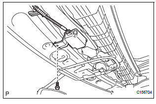
(a) Remove the bolt.
(b) Disconnect the connector and remove the tire pressure warning receiver assembly.
 Tire pressure warning receiver (w/ antenna)
Components
...
 Installation
1. INSTALL TIRE PRESSURE WARNING RECEIVER ASSEMBLY
(a) Connect the connector.
(b) Install the tire pressure warning receiver assembly
with the bolt.
Torque: 5.0 N*m (51 kgf*cm, 44 in.*lbf) ...
Other materials:
Compressor Lock Sensor Circuit
DTC B1422/22 Compressor Lock Sensor Circuit
SYSTEM DESCRIPTION
The ECM sends an engine speed signal to the A/C amplifier via CAN
communication and BEAN
communication.
The A/C amplifier reads the difference between compressor speed and engine
speed. When the
difference becomes too large, t ...
Terminals of ECU
1. COMBINATION METER ASSEMBLY
*1: with Power Rear No. 2 Seat with Stowing Function
*2: with Theft Deterrent System
Waveform 1 (Reference) : Using an oscilloscope:
OK:
HINT:
As vehicle speed increases, the cycle of the signal
waveform narrows.
Wavefor ...
Removal
1. RECOVER REFRIGERANT FROM REFRIGERATION
SYSTEM (See page AC-172)
2. REMOVE FRONT WIPER ARM HEAD CAP (See page
WW-4)
3. REMOVE FRONT WIPER ARM RH (See page WW-4)
4. REMOVE FRONT WIPER ARM LH (See page WW-4)
5. REMOVE COWL TOP VENTILATOR LOUVER SUBASSEMBLY
(See page WW-4)
6. REMOVE WINDSHIEL ...
