Toyota Sienna Service Manual: Installation
1. INSTALL TIRE PRESSURE WARNING RESET SWITCH
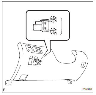
(a) Engage the 2 claws to install the tire pressure warning reset switch to the lower instrument panel finish panel sub-assembly LH.
2. INSTALL LOWER INSTRUMENT PANEL FINISH PANEL SUB-ASSEMBLY LH
3. INSTALL COWL SIDE TRIM SUB-ASSEMBLY LH
4. INSTALL FRONT DOOR SCUFF PLATE LH
5. CONNECT CABLE TO NEGATIVE BATTERY TERMINAL
6. INSPECT TIRE PRESSURE WARNING SYSTEM
HINT: See page TW-25.
 Inspection
1. INSPECT TIRE PRESSURE WARNING RESET SWITCH
(a) Remove the tire pressure warning reset switch.
(b) Measure the resistance between terminals 1 and 2
of the tire pressure warning reset switch ...
 Brake control
...
Other materials:
Short to B+ in Front Passenger Side Squib Circuit
DTC B0108/52 Short to B+ in Front Passenger Side Squib Circuit
DESCRIPTION
The front passenger side squib circuit consists of the center airbag sensor
assembly and the front
passenger airbag assembly.
The circuit instructs the SRS to deploy when deployment conditions are met.
DTC B0108/52 ...
Registering a Bluetooth®
audio player for the
first time
To use the Bluetooth® Audio, it is necessary to register an audio
player with the system.
Once the player has been registered, it is possible to use the
Bluetooth® Audio.
For details about registering a Bluetooth® device
Turn the Bluetooth® connection setting of your audio player on ...
Diagnosis system
1. DIAGNOSIS FUNCTION
The diagnosis function makes the light and the
multi-information display come on, and the CRUISE
main indicator light blink as shown in the illustration.
When a malfunction occurs in the dynamic laser
cruise control system, the DTCs are stored in the
ECM ...
