Toyota Sienna Service Manual: Tire pressure warning reset switch
COMPONENTS
 Installation
1. INSTALL TIRE PRESSURE WARNING ECU
(a) Connect the connector to the tire pressure warning
ECU.
(b) Install the tire pressure warning ECU with the screw.
2. INSTALL INSTRUMENT PANEL SAFET ...
 Removal
1. DISCONNECT CABLE FROM NEGATIVE BATTERY
TERMINAL
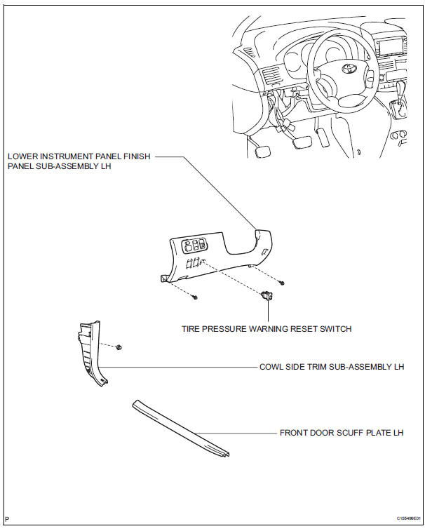
2. REMOVE FRONT DOOR SCUFF PLATE LH
3. REMOVE COWL SIDE TRIM SUB-ASSEMBLY LH
4. REMOVE LOWER INSTRUMENT PANEL FINISH
PANEL SUB-ASSEMBLY LH (See ...
Other materials:
System description
1. GENERAL
In conjunction with impact absorbing structure for a
frontal collision, the SRS (Supplemental Restraint
System) driver airbag and front passenger airbag
were designed to supplement seat belts in the event
of a frontal collision in order to help reduce shock to
the head ...
Display contents
The multi-information display presents
the driver with a variety of
vehicle data.
Menu icons
Displays the following information when an icon is selected.
Some of the information may be displayed automatically depending
on the situation.
Drive information
Select to display various ...
Removal
HINT:
Replace the RH side using the same procedures as for the
LH side.
1. REMOVE FRONT WHEEL
2. REMOVE FRONT AXLE HUB LH NUT (See page DS-
5)
3. SEPARATE SPEED SENSOR FRONT LH (See page
DS-5)
4. SEPARATE FRONT DISC BRAKE CALIPER ASSEMBLY LH
(a) Remove the 2 bolts and separate the front ...
