Toyota Sienna Service Manual: Diagnosis system
1. DIAGNOSIS FUNCTION
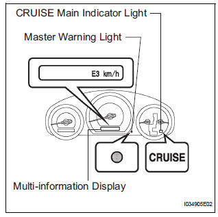
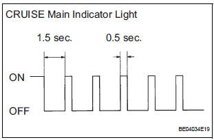
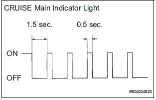
- The diagnosis function makes the light and the
multi-information display come on, and the CRUISE
main indicator light blink as shown in the illustration.
When a malfunction occurs in the dynamic laser cruise control system, the DTCs are stored in the ECM.
NOTICE:
- The master warning light goes off if the system returns to normal condition.
- Since the stored data in the ECM is erased by disconnecting the EFI and ETCS fuses or the battery terminal, do not disconnect them until the inspection has been completed.
2. DESCRIPTION
- The ECM controls the dynamic laser cruise control system of the vehicle. The data and DTCs relating to the dynamic laser cruise control system can be read from the DLC3 of the vehicle. If the CRUISE main indicator light does not come on after the DTC check, there may be a problem with either the combination meter or the CAN communication and multiplex communication systems. Use the intelligent tester to check and solve the problem.
3. CHECK DLC3
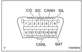
- The vehicle's ECM uses the ISO 15765-4 for communication protocol. The terminal arrangement of the DLC3 complies with SAE J1962 and matches the ISO 15765-4 format.
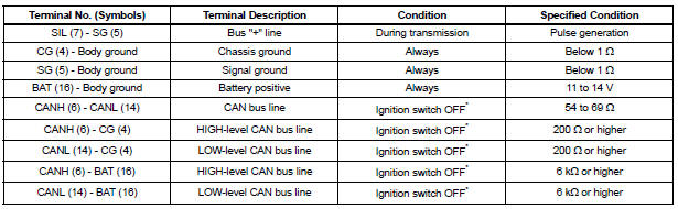
NOTICE: *: Before measuring the resistance, leave the vehicle for at least 1 minute and do not operate the ignition switch, any other switches, or doors.
If the result is not as specified, the DLC3 may have a malfunction. Repair or replace the harness and connector.
Connect the cable of the intelligent tester to the DLC3, turn the ignition switch to the ON position and attempt to use the tester. If the display indicates that a communication error has occurred, there is a problem either with the vehicle or with the tester.
- If communication is normal when the tester is connected to another vehicle, inspect the DLC3 of the original vehicle.
- If communication is still not possible when the tester is connected to another vehicle, the problem may be in the tester itself. Consult the Service Department listed in the tester's instruction manual.
4. CHECK INDICATOR
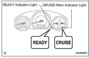
- Turn the ignition switch to the ON position.
- Check that the CRUISE main indicator light and READY indicator light come on when the cruise control main switch is turned on, and that the indicator lights go off when the main switch is turned off.
HINT:
- If the indicator check result shows a problem, proceed to troubleshooting for the combination meter section.
- If a malfunction occurs in the vehicle speed sensors, the stop light switch, or other related parts during cruise control driving, the ECU actuates AUTO CANCEL of the cruise control and blinks the CRUISE main indicator light. This indicator light informs the driver of the malfunction. At the same time, the malfunction is stored as a diagnostic trouble code.
 Terminals of ECU
1. CHECK DISTANCE CONTROL ECU
Reference: waveform 1
HINT:
Terminal: LRDD - SGND
Gauge set: 2 V/DIV., 10 ms./DIV.
Condition: ignition switch in the ON posit ...
 DTC check / clear
1. CHECK DTC
Connect the intelligent tester to the DLC3.
Connect the intelligent tester to the Controller
Area Network Vehicle Interface Module (CAN
VIM). Then connect th ...
Other materials:
Disassembly
1. REMOVE BACK DOOR GARNISH CENTER
Using a clip remover, disengage the 5 clips and
remove the garnish center.
2. REMOVE BACK DOOR SIDE GARNISH LH
Using a clip remover, disengage the 3 clips and
remove the side garnish.
3. REMOVE BACK DOOR SIDE GARNISH RH
Using a clip remove ...
ECM / PCM Internal Engine Off Timer Performance
DTC P2610 ECM / PCM Internal Engine Off Timer Performance
DTC SUMMARY
DESCRIPTION
To ensure the accuracy of the EVAP (Evaporative Emission) monitor values, the
soak timer, which is built
into the ECM, measures 5 hours (+/- 15 minutes) from when the ignition switch is
turned off, before t ...
Check component status
(a) Compare the test value with the minimum test limit
(MIN LIMIT) and maximum test limit (MAX LIMIT).
(b) If the test value is between the minimum test limit
and maximum test limit, the component is
functioning normally. If not, the component is
malfunctioning. The test value is usually sign ...
