Toyota Sienna Service Manual: Installation
1. INSTALL BRAKE ACTUATOR
(a) Install the brake actuator assembly with the 2 nuts.
Torque: 5.4 N*m (55 kgf*cm, 48 in.*lbf)
2. INSTALL BRAKE ACTUATOR WITH BRACKET
(a) Install the actuator with bracket with the 3 bolts.
Torque: 20 N*m (199 kgf*cm, 14 ft.*lbf)
NOTICE: Be careful not to damage the brake tubes and wire harness.
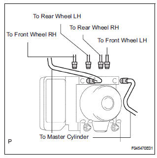
(b) Using SST, connect each brake tube to correct positions of the actuator with bracket, as shown in the illustration.
Torque: 15 N*m (155 kgf*cm, 11 ft.*lbf)
(c) Connect the brake actuator connector assembly.
3. INSTALL AIR CLEANER ASSEMBLY WITH HOSE
4. FILL RESERVOIR WITH BRAKE FLUID (See page BR- 3)
5. BLEED BRAKE MASTER CYLINDER SUBASSEMBLY (See page BR-3)
6. BLEED BRAKE LINE (See page BR-4)
7. CHECK BRAKE FLUID LEAKAGE
8. CHECK FLUID LEVEL IN RESERVOIR (See page BR- 7)
9. CONNECT BATTERY NEGATIVE TERMINAL
10. PERFORM INITIALIZATION
11. CHECK BRAKE ACTUATOR WITH INTELLIGENT TESTER
HINT: See page BC-183.
 Removal
1. DRAIN BRAKE FLUID
NOTICE:
Wash brake fluid off immediately if it adheres to any
painted surface.
2. DISCONNECT BATTERY NEGATIVE TERMINAL
3. REMOVE AIR CLEANER ASSEMBLY WITH HOSE
4. REMOVE BRA ...
Other materials:
How to proceed with
troubleshooting
HINT:
Troubleshoot in accordance with the procedures on the
following pages.
1 VEHICLE BROUGHT TO WORKSHOP
2 CUSTOMER PROBLEM ANALYSIS CHECK AND SYMPTOM CHECK
3 INSPECT COMMUNICATION FUNCTION OF LARGE-SCALE MULTIPLEX
COMMUNICATION SYSTEM (BEAN)
Use the intelligent tester to check for norma ...
Camshaft Position "B" - Timing Over
HINT:
If DTC P0014, P0015, P0024 or P0025 is present, check the VVT (Variable Valve
Timing) system.
DESCRIPTION
Refer to DTC P0013 (See page ES-87).
MONITOR DESCRIPTION
DTC P0014 and P0024
The ECM compares current valve timing with target valve timing, while the
engine is running a ...
Operation check
NOTICE: Inspection should be started after conforming that
the items listed in the "CUSTOMIZE PARAMETER" for the power back door system
have defaulted to the initial settings
1. CHECK OPENING OPERATION
Conditions necessary for the power back door to
open:
Power back d ...
