Toyota Sienna Service Manual: Removal
1. DRAIN BRAKE FLUID
NOTICE: Wash brake fluid off immediately if it adheres to any painted surface.
2. DISCONNECT BATTERY NEGATIVE TERMINAL
3. REMOVE AIR CLEANER ASSEMBLY WITH HOSE
4. REMOVE BRAKE ACTUATOR WITH BRACKET
(a) Release the latch of the brake actuator connector to disconnect the connector (b) Using SST, disconnect the 6 brake tubes from the actuator with bracket.
SST 09023-00101
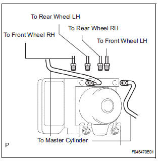
(c) Use tags or make a memo to identify the places to reconnect.
(d) Remove the 3 bolts and the actuator with bracket.
NOTICE: Be careful not to damage the brake tubes and wire harness.
5. REMOVE BRAKE ACTUATOR
(a) Remove the 2 nuts and the brake actuator assembly from the brake actuator bracket.
 On-vehicle inspection
1. CONNECT INTELLIGENT TESTER
(a) Connect the intelligent tester to the DLC3.
(b) Start the engine and run at idle.
(c) Select the ACTIVE TEST mode on the intelligent
tester.
HINT:
Pleas ...
 Installation
1. INSTALL BRAKE ACTUATOR
(a) Install the brake actuator assembly with the 2 nuts.
Torque: 5.4 N*m (55 kgf*cm, 48 in.*lbf)
2. INSTALL BRAKE ACTUATOR WITH BRACKET
(a) Install the actuator wit ...
Other materials:
Reassembly
1. INSTALL GENERATOR ROTOR ASSEMBLY
(a) Place the drive end frame on the clutch pulley.
(b) Install the generator rotor assembly to the drive end
frame.
(c) Place a new generator washer on the generator
rotor.
2. INSTALL GENERATOR COIL ASSEMBLY
(a) Using a deep socket wrench (21 ...
Installation
HINT:
Install the RH side by the same procedure as the LH side.
1. INSTALL REAR DISC BRAKE CYLINDER MOUNTING
LH
(a) Install the rear disc brake cylinder mounting LH with
the 2 bolts.
Torque: 88 N*m (900 kgf*cm, 65 ft.*lbf)
2. INSTALL REAR DISC BRAKE PAD SUPPORT PLATE
(a) Install the rear d ...
Exhaust gas precautions
Harmful substance to the human body is included in exhaust
gases if inhaled.
WARNINGExhaust gases include harmful carbon monoxide (CO),
which is colorless and
odorless. Observe the following precautions.
Failure to do so may cause exhaust gases enter the vehicle and may lead
...
