Toyota Sienna Service Manual: Installation
1. INSTALL COOLER CONDENSER CORE
(a) Install the cooler condenser core with the 2 screws.
Torque: 3.9 N*m (40 kgf*cm, 35 in.*lbf)
HINT: If the condenser is replaced with a new one, add compressor oil to the new condenser.
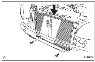
Capacity: 40 cc (1.4 fl.oz.) Compressor oil: ND-OIL 8 or equivalent
2. INSTALL NO. 1 RADIATOR SUPPORT (See page CO- 40)
3. INSTALL RADIATOR SUPPORT CUSHION (See page CO-41)
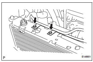
4. CONNECT NO. 2 OIL COOLER OUTLET TUBE SUBASSEMBLY
(a) Install the No. 2 oil cooler outlet tube sub-assembly with the 2 bolts.
Torque: 6.0 N*m (61 kgf*cm, 53 in.*lbf)
5. INSTALL UPPER RADIATOR SUPPORT SUBASSEMBLY (See page CO-42)
6. CONNECT COOLING FAN ECU (See page CO-42)
7. INSTALL HOOD LOCK SUPPORT SUB-ASSEMBLY (See page CO-43)
8. INSTALL HOOD LOCK ASSEMBLY (See page CO-43)
9. INSTALL HOOD LOCK RELEASE LEVER PROTECTOR (See page CO-44)
10. INSTALL NO. 1 AIR CLEANER INLET (See page EM- 59)
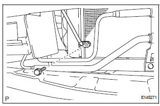
11. INSTALL COOLER REFRIGERANT LIQUID PIPE A
(a) Remove the attached vinyl tape from the pipe and the connecting part of the cooler condenser core.
(b) Sufficiently apply compressor oil to a new O-ring and the fitting surface of the pipe joint.
Compressor oil: ND-OIL 8 or equivalent
(c) Install the O-ring on the cooler refrigerant liquid pipe A.
(d) Install the cooler refrigerant liquid pipe A on the cooler condenser core with the bolt.
Torque: 5.4 N*m (55 kgf*cm, 47 in.*lbf)
12. INSTALL DISCHARGE HOSE SUB-ASSEMBLY
(a) Remove the attached vinyl tape from the tube and the connecting part of the cooler condenser core.
(b) Sufficiently apply compressor oil to a new O-ring and the fitting surface of the hose joint.
Compressor oil: ND-OIL 8 or equivalent
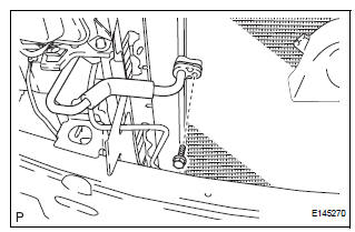
(c) Install the O-ring on the discharge hose subassembly.
(d) Install the discharge hose sub-assembly on the cooler condenser core with the bolt.
Torque: 5.4 N*m (55 kgf*cm, 47 in.*lbf)
13. INSTALL FRONT BUMPER ASSEMBLY (See page ET- 9)
14. INSTALL NO. 2 AIR CLEANER INLET (See page EM- 60)
15. CHARGE WITH REFRIGERANT (See page AC-173)
16. WARM UP ENGINE
17. INSPECT FOR REFRIGERANT LEAK (See page AC- 173)
18. VEHICLE PREPARATION FOR FOG LIGHT AIMING (w/ Fog Light) (See page LI-82)
19. PREPARATION FOR FOG LIGHT AIMING (w/ Fog Light) (See page LI-83)
20. FOG LIGHT AIMING INSPECTION (w/ Fog Light) (See page LI-84)
21. FOG LIGHT AIMING ADJUSTMENT (w/ Fog Light) (See page LI-85)
 Reassembly
1. INSTALL COOLER DRYER
(a) Using needle nose pliers, install the cooler dryer.
(b) Install a new O-ring on the cap.
(c) Sufficiently apply compressor oil to the fitting
surfaces of the ...
 Room temperature sensor
On-vehicle inspection
1. INSPECT A/C ROOM TEMPERATURE SENSOR
(a) Remove the A/C room temperature sensor.
(b) Measure the resistance according to the value(s) in
the table below.
Standard re ...
Other materials:
Operation check
NOTICE:
Inspection should be started after conforming that the
items listed in the "CUSTOMIZE PARAMETER" for the
power slide door system have defaulted to the initial
settings.
1. CHECK OPENING OPERATION
Conditions necessary for the power slide door to
open:
Power slid ...
Short to B+ in Front Passenger Side Squib 2nd
Step Circuit
DTC B1188/56 Short to B+ in Front Passenger Side Squib 2nd
Step Circuit
DESCRIPTION
The front passenger side squib 2nd step circuit consists of the center airbag
sensor assembly and the
front passenger airbag assembly.
The circuit instructs the SRS to deploy when deployment conditions are m ...
Installation
1. INSTALL TIRE PRESSURE WARNING ECU
(a) Connect the connector to the tire pressure warning
ECU.
(b) Install the tire pressure warning ECU with the screw.
2. INSTALL INSTRUMENT PANEL SAFETY PAD SUBASSEMBLY
HINT:
Refer to the instructions for INSTALLATION of the
instrument panel safety ...
