Toyota Sienna Service Manual: Back-up light assembly
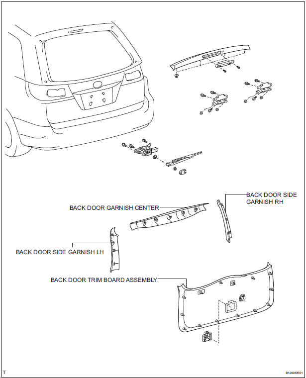
COMPONENTS
REMOVAL
1. REMOVE BACK DOOR GARNISH CENTER
2. REMOVE BACK DOOR SIDE GARNISH LH
3. REMOVE BACK DOOR SIDE GARNISH RH
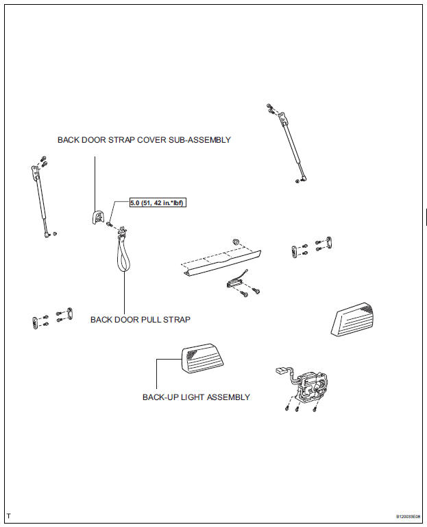
4. REMOVE BACK DOOR STRAP COVER SUBASSEMBLY
5. REMOVE BACK DOOR PULL STRAP
6. REMOVE BACK DOOR TRIM BOARD ASSEMBLY
7. REMOVE BACK-UP LIGHT ASSEMBLY
- Disconnect the connector.
- Release the 2 claw fittings and remove the 4 nuts and the back-up light assembly.
DISASSEMBLY
1. REMOVE BACK-UP LIGHT BULB
- Remove the back-up light bulb.
2. REMOVE BACK-UP LIGHT BULB
- Remove the back-up light bulb.
REASSEMBLY
1. INSTALL BACK-UP LIGHT BULB
- Install the back-up light bulb.
2. INSTALL BACK-UP LIGHT BULB
- Install the back-up light bulb.
INSTALLATION
1. INSTALL BACK-UP LIGHT ASSEMBLY
- Connect the connector.
- Install the back-up light assembly with the 4 nuts and 2 claws.
2. INSTALL BACK DOOR TRIM BOARD ASSEMBLY
3. INSTALL BACK DOOR PULL STRAP
4. INSTALL BACK DOOR STRAP COVER
5. INSTALL BACK DOOR SIDE GARNISH RH
6. INSTALL BACK DOOR SIDE GARNISH LH
7. INSTALL BACK DOOR GARNISH CENTER
 Rear combination light assembly
COMPONENTS
REMOVAL
1. DISCONNECT CABLE FROM NEGATIVE BATTERY
TERMINAL
2. REMOVE REAR COMBINATION LIGHT ASSEMBLY
Remove the 2 bolts.
Disengage the 2 pins and separate the ...
 License plate light assembly
COMPONENTS
REMOVAL
1. REMOVE BACK DOOR GARNISH CENTER
2. REMOVE BACK DOOR SIDE GARNISH LH
3. REMOVE BACK DOOR SIDE GARNISH RH
4. REMOVE BACK DOOR STRAP COVER
5. REMOVE BACK DOOR PULL STR ...
Other materials:
On-vehicle inspection
1. INSPECT CURTAIN SHIELD AIRBAG ASSEMBLY
(VEHICLE NOT INVOLVED IN COLLISION)
Perform a diagnostic system check.
With the curtain shield airbag assembly installed on
the vehicle, perform a visual check. If there are any
defects as mentioned below, replace the front pillar
...
Installing child restraints
Follow the child restraint system manufacturer’s instructions.
Firmly secure child restraints to the rear seats using the LATCH
anchors or a seat belt. Attach the top tether strap when installing
a child restraint.
The lap/shoulder belt can be used if your child restraint sy ...
Problem symptoms table
Use the table below to find the cause of the problem. The
numbers indicate the priority of the likely cause of the
problem. Check each part in order. If necessary, replace
these parts.
Front A/C:
Rear A/C:
...
