Toyota Sienna Service Manual: Installation
1. INSTALL STEERING PAD

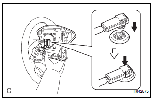
- Support the steering pad with one hand as shown in the illustration.
- Connect the 2 connectors to the steering pad.
NOTICE: When handling the airbag connector, take care not to damage the airbag wire harness.
- Connect the horn connector.
- Confirm that the circumference groove of the "torx" screw fits in the screw case, and place the steering pad onto the steering wheel assembly.
- Using a "torx" socket wrench (T30), tighten the 2 "torx" screws.
Torque: 8.8 N*m (90 kgf*cm, 78 in.*lbf)
2. INSTALL STEERING WHEEL NO.3 COVER LOWER
- Install the steering wheel No.3 cover lower.
3. INSTALL STEERING WHEEL NO.2 COVER LOWER
- Install the steering wheel No.2 cover lower.
4. CONNECT CABLE TO NEGATIVE BATTERY TERMINAL
5. INSPECT STEERING PAD

- With the steering pad installed on the vehicle, perform a visual check. If there are any defects as mentioned below, replace the steering pad with a new one: Cuts, minute cracks or marked discoloration on the steering pad top surface or in the grooved portion.
- Make sure that the horn sounds.
HINT: If the horn does not sound, inspect the horn system.
6. PERFORM INITIALIZATION
- Perform initialization.
HINT: Some systems need initialization when disconnecting the cable from the negative battery terminal.
7. INSPECT SRS WARNING LIGHT
- Inspect the SRS warning light
 Removal
1. PRECAUTION
CAUTION: Be sure to read "PRECAUTION" thoroughly before
servicing.
2. DISCONNECT CABLE FROM NEGATIVE BATTERY
TERMINAL
CAUTION:
Wait for 90 seconds after disconnecting th ...
 Disposal
HINT:
When scrapping a vehicle equipped with the SRS or
disposing of the steering pad, be sure to deploy the airbag
first in accordance with the procedure described below. If any
abnormality occur ...
Other materials:
Data list / active test
1. DATA LIST
HINT:
Using the DATA LIST displayed on the intelligent tester,
you can read the value of the switch, sensor, actuator,
etc. without parts removal. Reading the DATA LIST as
the first step of troubleshooting is one way to shorten the
labor time.
Connect the intelligent tester to ...
Precaution
1. REMOVAL AND INSTALLATION OF THE BATTERY TERMINAL
Before performing electrical work, disconnect the
battery negative (-) terminal in order to prevent a
short in the system.
When disconnecting and reconnecting the battery
cable, turn the ignition switch and lighting swit ...
Removal
1. Drain automatic transaxle fluid
(a) Remove the drain plug, gasket and drain ATF.
(b) Install a new gasket and the drain plug.
Torque: 49 N*m (500 kgf*cm, 36 ft.*lbf)
2. Drain transfer oil (for 4wd)
Hint:
(see page tf-8)
3. Remove front wheel
4. REMOVE FRONT AXLE HUB LH NUT
(a) Us ...
