Toyota Sienna Service Manual: Television Display Assembly Communication Error
INSPECTION PROCEDURE
1 IDENTIFY THE COMPONENT SHOWN BY THE SUB-CODE
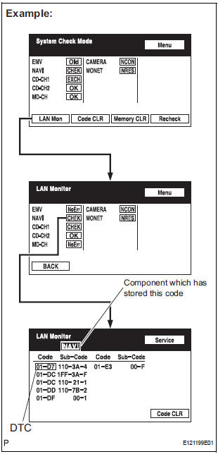
- Enter the diagnostic mode.
- Press the "LAN Mon" switch to change to "LAN Monitor" mode.
- Identify the component shown by the sub-code.
HINT:
- "110 (multi-display)" is the component shown by the sub-code in the example shown in the illustration.
- The sub-code will be indicated by its physical address.
- For the component list, refer to "DIAGNOSIS DISPLAY DETAILED DESCRIPTION"
2 CHECK POWER SOURCE CIRCUIT OF COMPONENT SHOWN BY SUB-CODE
- Inspect the power source circuit of the component shown
by the sub-code.
If the power source circuit is operating normally, proceed to the next step.
Component Table:

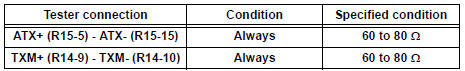
3 INSPECT RADIO AND NAVIGATION ASSEMBLY
- Disconnect the radio and navigation assembly connectors.
- Measure the resistance according to the value(s) in the table below.
Standard resistance
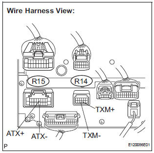
4 CHECK HARNESS AND CONNECTOR
HINT:
- Start the check from the circuit that is near the component shown by the sub-code first.
- For details of the connectors, refer to "TERMINALS OF ECU".
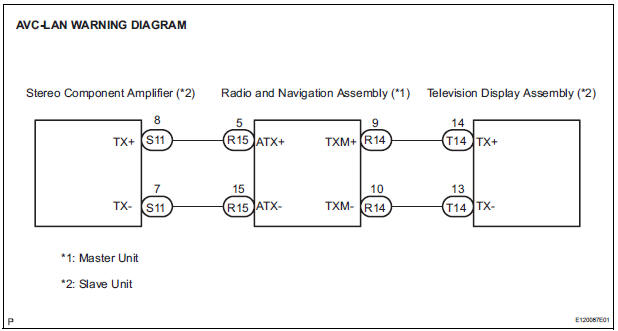
- Referring to the AVC-LAN wiring diagram below, check the AVC-LAN circuit between the television display assembly and the component shown by the sub-code.
- Disconnect all connectors between the television display assembly and the component shown by sub-code.
- Check for an open or short in the AVC-LAN circuit between the television display assembly and the component shown by the sub-code.
OK: There is no open or short circuit.
5 REPLACE COMPONENT SHOWN BY SUB-CODE
- Replace the component shown by the sub-code with a normal one and check if the same problem occurs again.
OK: Same problem does not occur
END
 Radio and Navigation Assembly Communication Error
INSPECTION PROCEDURE
1 IDENTIFY THE COMPONENT SHOWN BY THE SUB-CODE
Enter the diagnostic mode.
Press the "LAN Mon" switch to change to "LAN Monitor"
mode.
&nbs ...
 Stereo Component Amplifier Power Source Circuit
DESCRIPTION
This circuit provides power to the stereo component amplifier.
WIRING DIAGRAM
INSPECTION PROCEDURE
1 INSPECT STEREO COMPONENT AMPLIFIER
Disconnect the stereo component ampl ...
Other materials:
Noise Occurs
INSPECTION PROCEDURE
1 NOISE CONDITION
Check in which direction the noise comes from (front left
or right, or rear left or right).
Check in which direction the noise comes from.
OK:
The location of the noise source can be
determined
2 CHECK SPEAKERS
Check the installation cond ...
Removal
1. DISCHARGE FUEL SYSTEM PRESSURE
HINT:
See page FU-1.
2. DISCONNECT CABLE FROM NEGATIVE BATTERY
TERMINAL
3. REMOVE NO. 1 ENGINE UNDER COVER
4. DRAIN ENGINE COOLANT (See page CO-6)
5. REMOVE FRONT WIPER ARM HEAD CAP (See page
WW-4)
6. REMOVE FRONT WIPER ARM RH (See page WW-4)
7. REMOVE FRO ...
Fold Seat Switch Circuit
DESCRIPTION
When the fold seat switch is operated, a switch operation signal is sent to
the fold seat control ECU. The
ECU receives switch operation signals from each switch and activates the folding
motor, reclining motor,
and release actuator.
WIRING DIAGRAM
INSPECTION PROCEDURE
1 IN ...
