Toyota Sienna Service Manual: Installation
1. INSTALL FRONT BUMPER ASSEMBLY
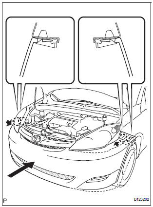
- Push the front bumper onto the front of the vehicle and engage the claws on the left and right sides of the front bumper to install it as shown in the illustration.
HINT:
- Apply protective tape to the bottom part of the front fender to prevent it from being damaged.
- Connect the connectors if necessary.
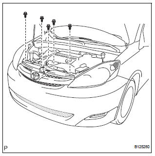
- Install the 5 clips.
- Connect the engine under cover to the front bumper
assembly with the 8 screws.
Torque: 7.0 N*m (71 kgf*cm, 62.0 in.*lbf)

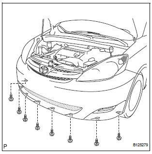
- Connect the fender liner to the front bumper assembly with the 4 screws.
2. CONNECT CABLE TO NEGATIVE BATTERY TERMINAL
3. VEHICLE PREPARATION FOR FOG LIGHT AIMING (w/ Fog Light) (See page LI-82)
4. PREPARATION FOR FOG LIGHT AIMING (w/ Fog Light) (See page LI-83)
5. FOG LIGHT AIMING INSPECTION (w/ Fog Light) (See page LI-84)
6. FOG LIGHT AIMING ADJUSTMENT (w/ Fog Light)
 Reassembly
1. INSTALL LOWER RADIATOR GRILLE
Engage the 16 claws to install the lower radiator
grille to the front bumper cover.
2. INSTALL FRONT BUMPER HOLE COVER LH (w/o
Fog Light)
Engage ...
 Rear bumper
COMPONENTS
...
Other materials:
Removal
1. REMOVE INSTRUMENT CLUSTER CENTER NO. 1 FINISH PANEL
2. REMOVE INSTRUMENT CLUSTER CENTER NO. 2
FINISH PANEL
3. REMOVE SHIFT LEVER KNOB SUB-ASSEMBLY
4. REMOVE POSITION INDICATOR HOUSING ASSEMBLY
5. REMOVE INSTRUMENT CLUSTER CENTER LOWER FINISH PANEL SUB-ASSEMBLY
6. REMOVE CIGARETTE LIGHTER CO ...
Bluetooth® Audio
Listening to Bluetooth® Audio
The Bluetooth® audio system enables the user to enjoy music
played on a portable player from the vehicle speakers via wireless
communication.
When a Bluetooth® device cannot be connected, check the connection
status on the “Bluetooth* Audio” screen. If the ...
Air Intake Control Circuit
DESCRIPTION
The air cleaner is equipped with two inlets, one of which is opened or closed
by the Air Intake Control
Valve (AICV). This system reduces intake noise and increases engine power at
low-to-high engine speed
range.
When the engine is operating in the low-to-mid speed range, this ...
