Toyota Sienna Service Manual: Installation
1. INSTALL FRONT SHOULDER BELT ANCHOR ADJUSTER ASSEMBLY
- Install the front shoulder belt anchor adjuster
assembly with the bolt.
Torque: 42 N*m (430 kgf*cm, 31 ft.*lbf)
2. INSTALL CENTER PILLAR UPPER GARNISH
3. INSTALL FRONT SEAT OUTER BELT ASSEMBLY
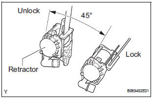
NOTICE: Do not disassemble the retractor.
- Check the degree of tilt when beginning to lock the ELR.
- Check that the belt does not lock within 15
degrees of tilt in all directions but that the belt
locks with over 45 degrees of tilt, when gently
moving the retractor.
If operation is not as specified, replace the front seat outer belt assembly.
- Install the retractor with the 2 bolts.
Torque: 42 N*m (430 kgf*cm, 31 ft.*lbf)
- Install the shoulder anchor with the nut.
Torque: 42 N*m (430 kgf*cm, 31 ft.*lbf)
- Install the floor anchor with the bolt.
Torque: 42 N*m (430 kgf*cm, 31 ft.*lbf)
- Install the floor anchor cover.
- Check the ELR lock.
NOTICE: The check should be performed with the assembly installed.
- Check that the belt locks when pulling out the
belt quickly when the belt is installed.
If operation is not as specified, replace the front seat outer belt assembly.
- Check the fastening function of the child restraint system.
NOTICE: The check should be performed with the assembly installed.
- Check that the belt cannot be pulled out any more but can be rewound after the belt is fully pulled out.
- Check that the belt can be pulled out and
rewound after the belt is fully rewound.
If operation is not as specified, replace the front seat outer belt assembly.
4. INSTALL CENTER PILLAR LOWER GARNISH
5. INSTALL FRONT DOOR WEATHERSTRIP
6. INSTALL REAR DOOR WEATHERSTRIP
7. INSTALL FRONT DOOR SCUFF PLATE
8. INSTALL REAR DOOR SCUFF PLATE
9. INSTALL FRONT SEAT ASSEMBLY
HINT:
- Refer to the instructions for installation of the front seat assembly (for flat type).
- Refer to the instructions for installation of the front seat assembly (for manual seat).
- Refer to the instructions for installation of the front seat assembly (for power seat).
10. CONNECT CABLE TO NEGATIVE BATTERY TERMINAL
11. PERFORM INITIALIZATION
HINT: Some systems need initialization when disconnecting the cable from the negative battery terminal
 Removal
1. DISCONNECT CABLE FROM NEGATIVE BATTERY
TERMINAL
CAUTION:
Wait for 90 seconds after disconnecting the cable to prevent the airbag working
2. REMOVE FRONT SEAT ASSEMBLY
HINT:
Refer to ...
 Disposal
1. DISPOSE OF FRONT SEAT OUTER BELT ASSEMBLY (WHEN INSTALLED IN VEHICLE)
NOTICE:
Never dispose of a front seat outer belt assembly
with an deactivated pretensioner.
The seat belt ...
Other materials:
Reassembly
1. INSTALL FRONT DISC
(a) Aligning the matchmarks, install the front disc.
HINT:
Select the installation position where the disc has
the minimum runout.
2. INSPECT DISC RUNOUT
(a) Temporarily fasten the disc with the hub nuts.
Torque: 103 N*m (1,050 kgf*cm, 76 ft.*lbf)
(b) Using a ...
Connecting a Bluetooth®
device
Up to 5 Bluetooth® devices (Phones [HFP] and audio players
[AVP]) can be registered.
If more than 1 Bluetooth® device has been registered, select
which device to connect to.
Press the “SETUP” button.
Select “Bluetooth*”.
*: Bluetooth is a registered trademark of Bluetooth SI ...
Open in Driver Side Squib 2nd Step Circuit
DTC B1181/18 Open in Driver Side Squib 2nd Step Circuit
DESCRIPTION
The driver side squib 2nd step circuit consists of the center airbag sensor
assembly, the spiral cable and
the steering pad.
The circuit instructs the SRS to deploy when deployment conditions are met.
DTC B1181/18 is reco ...
