Toyota Sienna Service Manual: SFR Solenoid Circuit
DESCRIPTION
The solenoid comes on when signals are received from the ECU and controls the pressure acting on the wheel cylinders, thus controlling brake force.
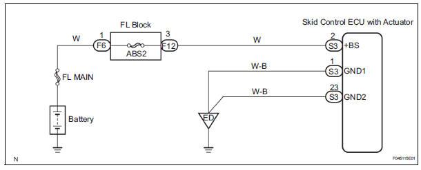
WIRING DIAGRAM
INSPECTION PROCEDURE
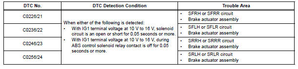
1 RECONFIRM DTC
HINT: These codes are detected when a problem is identified in the brake actuator.
The solenoid circuit is in the brake actuator.
Therefore, solenoid circuit inspection and solenoid unit inspection cannot be performed. Be sure to check if any DTC is output before replacing the brake actuator assembly.
(a) Clear the DTCs (See page BC-10).
(b) Start the engine.
(c) Drive the vehicle at the speed of 4 mph (6 km/h) or more.
(d) Check that the same DTCs are recorded (See page BC- 10).
HINT: If a speed signal of 4 mph (6 km/h) or more is input to the skid control ECU, with the ignition switch on and the stop light switch off, the ECU performs self-diagnosis of the motor and solenoid circuits.
Result 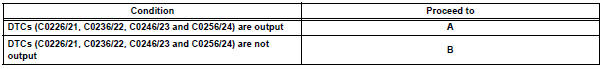
HINT:
- If any DTCs are output while jiggling a connector or wire harness of the brake actuator (skid control ECU), inspect and repair the connector or wire harness.
- If the normal system code is output, slightly jiggle the connectors, wire harnesses, and fuses of the brake actuator assembly. Make sure that no DTCs are output.
- These DTCs may be stored due to a malfunction in the connector terminal connection, etc.


REPLACE BRAKE ACTUATOR ASSEMBLY
 Rear Speed Sensor RH Circuit
DESCRIPTION
Refer to DTCs C0200/31, C0205/32, C1235/35, and C1236/36 (See page BC-17).
DTCs C1273/73 to C1278/78 can be deleted when the speed sensor sends a vehicle
speed signal or the
Tes ...
 Open in ABS Motor Relay Circuit
DESCRIPTION
The ABS motor relay supplies power to the ABS pump motor. While the ABS is
activated, the ECU turns
the motor relay on and operates the ABS pump motor.
If the voltage supplied t ...
Other materials:
Installation
1. INSTALL POWER POINT SOCKET ASSEMBLY
Engage the 2 claws to install the power point socket
assembly.
2. INSTALL QUARTER TRIM FRONT PANEL ASSEMBLY
LH
3. INSTALL BACK DOOR SCUFF PLATE
4. INSTALL BACK DOOR WEATHERSTRIP
5. INSTALL REAR DOOR WEATHERSTRIP LH
6. INSTALL REAR DOOR S ...
Removal
1. REMOVE ROOF DRIP SIDE FINISH MOULDING
Put protective tape around the roof drip side finish
moulding.
Using a remover for the roof moulding, disengage of
the clips both in the front and rear ends of the roof
drip side finish moulding and then remove the roof
drip side finish moul ...
Problem symptoms table
WINDOW DEFOGGER SYSTEM
Symptom
Suspected area
w/ Deicer: Front window deicer does not operate.
(indicator light ON)
FR DEF fuse
Front window deicer relay
Front window deicer wire
Wire harness
w/ deicer: Front window deicer ...
