
Toyota Sienna Service Manual: Installation
1. INSTALL THROTTLE BODY
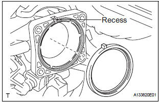
- Install a new throttle body gasket to the intake air surge tank.
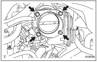
- Install the throttle body with the 4 bolts.
Torque: 10 N*m (102 kgf*cm, 7 ft.*lbf)
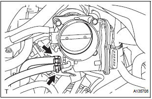
- Connect the 2 water by-pass hoses.
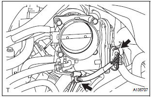
- Connect the throttle body connector and clamp.
2. INSTALL AIR CLEANER CASE SUB-ASSEMBLY
3. INSTALL AIR CLEANER CAP SUB-ASSEMBLY
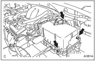
- Install the air cleaner cap sub-assembly with the 2 bolts.
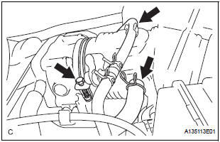
- Connect the the vacuum hose (EVAP) to the air cleaner hose.
- Install the No. 2 ventilation hose and air cleaner hose band.
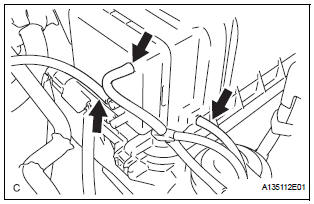
- Connect the 3 vacuum hoses.
4. INSTALL NO. 1 AIR CLEANER INLET
5. INSTALL NO. 2 AIR CLEANER INLET
6. ADD ENGINE COOLANT
7. INSPECT FOR ENGINE COOLANT LEAK
8. INSTALL V-BANK COVER SUB-ASSEMBLY
9. INSTALL FRONT OUTER COWL TOP PANEL SUBASSEMBLY
10. INSTALL WINDSHIELD WIPER MOTOR ASSEMBLY
 Inspection
1. INSPECT THROTTLE BODY
Using an ohmmeter, measure the resistance
between the terminals.
Standard resistance
If the result is not as specified, replace the throttle
body asse ...
 ECM
ECM
Components
...
Other materials:
Blower Motor Circuit
DESCRIPTION
The blower motor is operated by signals from the A/C amplifier. Blower motor
speed signals are
transmitted by changes in the Duty Ratio.
Duty Ratio
The duty ratio is the ratio of the period of continuity in one cycle. For
example, if A is the period of
continuity in one cycl ...
Inspection
1. INSPECT FRONT SEAT INNER BELT ASSEMBLY RH
Release the seat belt (Buckle switch is ON).
Check the resistance between the terminals.
Standard
If the result is not as specified, replace the inner belt
assembly.
Inspect the buckle switch.
Fasten ...
Short in Front Passenger Side Squib 2nd Step
Circuit
DTC B1185/57 Short in Front Passenger Side Squib 2nd Step
Circuit
DESCRIPTION
The front passenger side squib 2nd step circuit consists of the center airbag
sensor assembly and the
front passenger airbag assembly.
The circuit instructs the SRS to deploy when deployment conditions are met.
...
