Toyota Sienna Service Manual: Installation
1. INSTALL SEAT POSITION AIRBAG SENSOR
- Check that the ignition switch is off.
- Check that the negative battery (-) terminal is
disconnected.
CAUTION: After disconnecting the negative battery terminal, wait for at least 90 seconds before starting the operation.
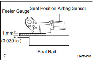
- Using a feeler gauge 1 mm (0.039 in.), install the seat position sensor.
NOTICE:
- If the seat position sensor has been dropped, or there are any cracks, dents or other defects in the case or connector, replace it with a new one.
- When installing the seat position sensor, be careful that the SRS wiring does not interfere with other parts and that it is not pinched between other parts.
HINT: Be sure that a clearance between the seat position sensor and the seat rail is within 0.6 mm (0.023 in.) to 1.4 mm (0.055 in.).
- Using a "torx" socket wrench (T30), tighten the
"torx" screw to install the seat position sensor.
Torque: 8.0 N*m (82 kgf*cm, 71 in.*lbf)
- Make sure that a clearance between the seat position sensor and the seat rail is within 0.6 mm (0.023 in.) to 1.4 mm (0.055 in.).
- Check that there is no looseness in the installation parts of the seat position sensor.
- Connect the connector to the seat position sensor.
2. INSTALL SEAT SLIDE POSITION SENSOR PROTECTOR
3. INSTALL FRONT SEAT CUSHION SHIELD ASSEMBLY (for Power Seat)
4. INSTALL SLIDE AND VERTICAL POWER SEAT SWITCH KNOB (for Power Seat)
5. INSTALL RECLINING POWER SEAT SWITCH KNOB (for Power Seat)
6. INSTALL FRONT SEAT CUSHION SHIELD LH (for Manual Seat)
7. INSTALL VERTICAL ADJUSTING HANDLE NO.2 (for Manual Seat)
8. INSTALL VERTICAL SEAT ADJUSTER KNOB CAP (for Manual Seat)
9. INSTALL RECLINING ADJUSTER RELEASE HANDLE LH (for Manual Seat)
10. INSTALL FRONT SEAT ASSEMBLY (for Manual Seat)
11. INSTALL FRONT SEAT ASSEMBLY (for Power Seat)
12. CONNECT CABLE TO NEGATIVE BATTERY TERMINAL
13. PERFORM INITIALIZATION
- Perform initialization.
HINT: Some systems need initialization when disconnecting the cable from the negative battery terminal.
14. INSPECT SLIDE ADJUSTER LOCK (for Manual Seat)
15. INSPECT POWER SEAT OPERATION (for Power Seat)
16. INSPECT SEAT HEATER OPERATION (w/ Seat Heater System)
17. INSPECT SRS WARNING LIGHT
- Inspect the SRS warning light
 On-vehicle inspection
1. INSPECT SEAT POSITION SENSOR (VEHICLE NOT
INVOLVED IN COLLISION)
Perform a diagnostic system check.
2. INSPECT SEAT POSITION SENSOR (VEHICLE
INVOLVED IN COLLISION)
Perform ...
 Occupant classification ecu
COMPONENTS
...
Other materials:
Short to B+ in Front Pretensioner Squib LH Circuit
DTC B0138/72 Short to B+ in Front Pretensioner Squib LH Circuit
DESCRIPTION
The front pretensioner squib LH circuit consists of the center airbag sensor
assembly and the front seat
outer belt assembly LH.
This circuit instructs the SRS to deploy when deployment conditions are met.
DTC B01 ...
Installation
HINT:
Use the same procedures for the RH side and LH side.
The procedures listed below are for the LH side.
1. INSTALL REAR AIRBAG SENSOR LH
Check that the ignition switch is off.
Check that the battery negative (-) terminal is
disconnected.
CAUTION:
...
Customer problem analysis
HINT:
In troubleshooting, confirm that the problem symptoms
have been accurately identified. Preconceptions should be
discarded in order to make an accurate judgment. To
clearly understand what the problem symptoms are, it is
extremely important to ask the customer about the
problem an ...
