Toyota Sienna Service Manual: Installation
1. INSTALL TRANSFER RH BEARING RETAINER OIL SEAL
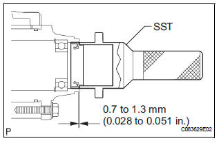
(a) Using SST, install a new transfer RH bearing retainer oil seal to the transfer case at the position as show in the illustration.
SST 09223-46011
NOTICE: Do not install the oil seal obliquely
(b) Apply small amount of MP grease to the oil seal lip.
2. INSTALL FRONT DRIVE SHAFT ASSEMBLY RH
HINT: (See page DS-17)
3. INSTALL FRONT WHEEL Torque: 103 N*m (1,050 kgf*cm, 76 ft.*lbf)
4. ADD AUTOMATIC TRANSAXLE FLUID
5. INSTALL TRANSFER DRAIN PLUG
(a) Install the transfer drain plug with a new drain gasket.
Torque: 49 N*m (500 kgf*cm, 36 ft.*lbf)
6. INSTALL NO. 1 TRANSFER CASE PLUG
(a) Add oil up 0 to 5 mm (0 to 0.20 in.) below the lower side of the plug hole.
Oil amount : 0.9 L (0.95 US qts, 0.71 lmp.qts)
HINT: When adding oil, pour it slowly.
(b) Install the No. 1 transfer case plug with a new No. 1 gasket.
Torque: 49 N*m (500 kgf*cm, 36 ft.*lbf)
7. CHECK FOR EXHAUST GAS LEAK
8. INSPECT AND ADJUST FRONT WHEEL ALIGNMENT
HINT: (See page SP-4)
9. CHECK ABS SPEED SENSOR SIGNAL
HINT: (See page BC-3)
 Removal
1. DRAIN AUTOMATIC TRANSAXLE FLUID (See page
AX-131)
2. REMOVE NO. 1 TRANSFER CASE PLUG (See page
TF-8)
3. REMOVE TRANSFER DRAIN PLUG
(a) Remove the transfer drain plug, gasket and bleed
the dra ...
 Transfer assembly
COMPONENTS
...
Other materials:
Customize parameters
HINT:
The following items can be customized.
NOTICE:
After confirming whether the items requested by the
customer are applicable or not for customization,
perform the customize operation.
Be sure to record the current settings before
customizing.
When troubleshootin ...
Slip Indicator Light Remains ON
DESCRIPTION
The skid control ECU is connected to the combination meter via CAN and
multiplex communications.
The SLIP indicator blinks during VSC and/or TRAC operation.
When the system fails, the SLIP indicator comes on to warn the driver.
WIRING DIAGRAM
INSPECTION PROCEDURE
NOTICE:
...
Front Occupant Classification Sensor LH Circuit
Malfunction
DTC B1780 Front Occupant Classification Sensor LH Circuit
Malfunction
DESCRIPTION
The front occupant classification sensor LH circuit consists of the occupant
classification ECU and the
front occupant classification sensor LH.
DTC B1780 is recorded when a malfunction is detected in the fron ...
