Toyota Sienna Service Manual: ECM / PCM Processor
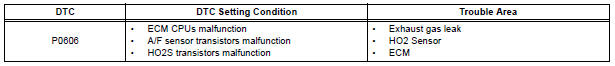
DTC P0606 ECM / PCM Processor
DESCRIPTION
The ECM continuously monitors its internal processors (CPUs), A/F sensor transistors and heated oxygen sensor (HO2S) transistors. This self-check ensures that the ECM is functioning properly. These are diagnosed by internal "mirroring" of the main and sub CPUs to detect the processors error. If outputs from the processors deviate from the standards, the ECM will illuminate the MIL and set a DTC immediately.
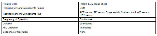
MONITOR STRATEGY
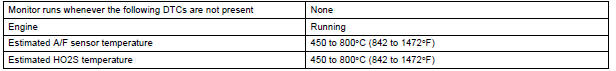
TYPICAL ENABLING CONDITIONS
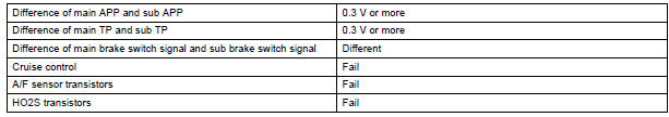
TYPICAL MALFUNCTION THRESHOLDS
INSPECTION PROCEDURE
1 INSPECT FOR EXHAUST GAS LEAK
- Allow the engine to idle.
- Check for exhaust gas leak around the heated oxygen sensor.
OK: No leak from the heated oxygen sensor.
2 CHECK HEATED OXYGEN SENSOR
- Connect the intelligent tester to the DLC3.
- Start the engine and turn the tester on.
- Warm up the engine at an engine speed of 2500rpm for approximately 90 seconds.
- Enter the following menus: DIAGNOSIS / ENHANCED II / ACTIVE TEST / A/F CONTROL.
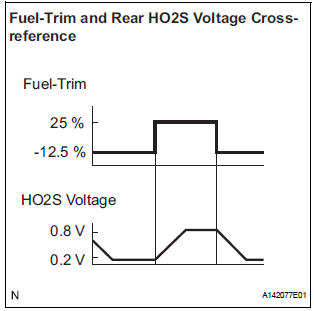
- Perform the A/F CONTROL operation with the engine in an idling condition (press the RIGHT or LEFT button to change the fuel injection volume).
- Monitor the voltage outputs of the HO2 sensors (O2S B1S2) displayed on the tester.
HINT:
- The A/F CONTROL operation lowers the fuel injection volume by 12.5% or increases the injection volume by 25%.
- Each sensor reacts in accordance with increases in the fuel injection volume.
Standard voltage
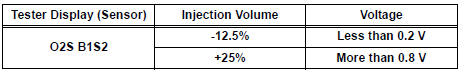
Result
3 CHECK WHETHER DTC OUTPUT RECURS (IN ADDITION TO DTC P0606)
- Connect the intelligent tester to the DLC3.
- Turn the ignition switch to the ON position.
- Turn the tester on.
- Clear the DTC.
- Turn the ignition switch off.
- Disconnect the battery negative terminal and wait for 1 minute.
- Connect the battery negative terminal.
- Start the engine.
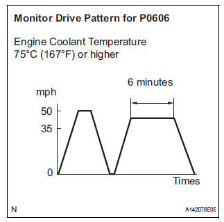
- Perform the drive pattern.
- Warm up the engine.
- Accelerate the vehicle to 50 mph (80 km/h) and stop the vehicle.
- Drive the vehicle at 35 to 50 mph (60 to 80 km/h) for 5 minutes or more.
- Enter the following menus: DIAGNOSIS / ENHANCED II / DTC INFO / CURRENT CODES.
- Read the DTCs.
Result
REPLACE ECM
 Internal Control Module Random Access Memory
(RAM) Error
Internal Control Module Random Access Memory
(RAM) Error
DTC P0604 Internal Control Module Random Access Memory
(RAM) Error
DESCRIPTION
The ECM continuously monitors its own internal memory status, internal
circuits, and output signals
transmitted to ...
 Control Module Performance
DTC P0607 Control Module Performance
DESCRIPTION
The ECM continuously monitors its main and sub CPUs. This self-check ensures
that the ECM is
functioning properly. If outputs from the CPUs are di ...
Other materials:
Disassembly
1. Remove park/neutral position switch assembly
(A) remove the nut, washer and control shaft lever.
(B) using a screwdriver, unstake the nut stopper, and
remove the lock nut and nut stopper.
(c) Remove the 2 bolts and pull out the park/neutral
position switch.
2. REMOVE BREATHER PLUG H ...
Personal/interior
lights
Front
Turns the light on/off
Rear
Turns the light on/off
When the personal/interior light main switch is in the off position, the
rear personal lights will not turn on even if the switch is on.
Type A
Type B
...
Headlight leveling switch
ON-VEHICLE INSPECTION
1. HEADLIGHT LEVELING SWITCH
Connect the battery positive (+) lead to the terminal
1 and the battery negative (-) lead to the terminal 5.
Measure the resistance between the terminal 4 and
the battery negative (-) lead when headlight leveling
switch ...
