Toyota Sienna Service Manual: Installation
1. INSTALL TRANSFER ASSEMBLY
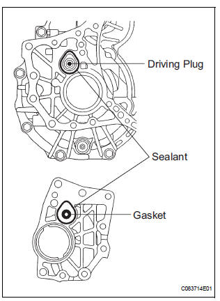
(a) Apply sealant 1281 to the transaxle assembly and transfer assembly in continuous beaded from of 1.2 mm diameter as shown in the illustration.
NOTICE:
- Wipe any grease off from the attaching surfaces.
- Install it within 10 minutes after applying the sealant.
- Sealant stuck on the gasket, case oil seal and driving plug may cause oil leakage and seizure due to oil shortage. Care must be taken.
(b) Install the transfer assembly to the transaxle assembly with the 2 bolts and 6 nuts.
Torque: 69 N*m (700 kgf*cm, 51 ft.*lbf)
NOTICE:
- Check that the gasket is installed to the transfer assembly before installing them to the transaxle assembly.
- Install the transfer assembly to the transaxle assembly without tilting.
- When moving the transfer assembly, do not hold the oil seal on the both sides.
2. INSTALL AUTOMATIC TRANSMISSION WITH TRANSFER
HINT: (See page AX-167)
3. INSTALL ENGINE AND TRANSAXLE
HINT: (See page EM-44)
4. INSTALL TRANSFER DRAIN PLUG
(a) Install the transfer drain plug with a new drain gasket.
Torque: 49 N*m (500 kgf*cm, 36 ft.*lbf)
5. INSTALL NO. 2 TRANSFER CASE PLUG
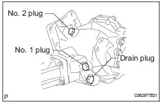
(a) Install the No. 2 transfer case plug with a new No. 2 gasket.
Torque: 49 N*m (500 kgf*cm, 36 ft.*lbf)
6. INSTALL NO. 1 TRANSFER CASE PLUG
(a) Add oil up to 0 to 5 mm below the lower side of the plug hole.
Oil quantity: 0.9 L (0.95 US qts, 0.71 lmp. qts)
HINT: When adding oil, pour it slowly.
(b) Install the No. 1 transfer case plug with a new No. 1 gasket.
Torque: 49 N*m (500 kgf*cm, 36 ft.*lbf)
7. INSPECT AND ADJUST FRONT WHEEL ALIGNMENT
HINT: (See page SP-4)
8. CHECK ABS SPEED SENSOR SIGNAL
HINT: (See page BC-3)
 Removal
1. REMOVE ENGINE AND TRANSAXLE
HINT:
(See page EM-26)
2. REMOVE AUTOMATIC TRANSMISSION WITH
TRANSFER
HINT:
(See page AX-164)
3. REMOVE NO. 1 TRANSFER CASE PLUG
(a) Remove the No. 1 transfe ...
 Transfer unit
COMPONENTS
...
Other materials:
Open in Front Passenger Side Squib 2nd Step
Circuit
DTC B1186/58 Open in Front Passenger Side Squib 2nd Step
Circuit
DESCRIPTION
The front passenger side squib 2nd step circuit consists of the center airbag
sensor assembly and the
front passenger airbag assembly.
The circuit instructs the SRS to deploy when deployment conditions are met.
...
Installation
1. INSTALL TIRE PRESSURE WARNING RESET SWITCH
(a) Engage the 2 claws to install the tire pressure
warning reset switch to the lower instrument panel
finish panel sub-assembly LH.
2. INSTALL LOWER INSTRUMENT PANEL FINISH
PANEL SUB-ASSEMBLY LH
3. INSTALL COWL SIDE TRIM SUB-ASSEMBLY LH
4. IN ...
Ignition Coil "A" Primary
HINT:
These DTCs indicate malfunctions relating to the primary circuit.
If DTC P0351 is set, check the No. 1 ignition coil with igniter circuit.
If DTC P0352 is set, check the No. 2 ignition coil with igniter circuit.
If DTC P0353 is set, check the No. 3 ignition coil with igniter circ ...
