Toyota Sienna Service Manual: Removal
1. REMOVE ENGINE AND TRANSAXLE
HINT: (See page EM-26)
2. REMOVE AUTOMATIC TRANSMISSION WITH TRANSFER
HINT: (See page AX-164)
3. REMOVE NO. 1 TRANSFER CASE PLUG
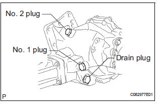
(a) Remove the No. 1 transfer case plug.
(b) Remove the No. 1 gasket from the transfer case No.
1 plug.
4. REMOVE NO. 2 TRANSFER CASE PLUG
(a) Remove the No. 2 transfer case plug.
(b) Remove the No. 2 gasket from the No. 2 transfer case plug.
5. REMOVE TRANSFER DRAIN PLUG
(a) Remove the transfer drain plug and bleed the oil.
(b) Remove the drain gasket from the transfer drain plug.
6. REMOVE TRANSFER ASSEMBLY
(a) Remove the 2 bolts and 6 bolts.
(b) Using a plastic hammer, remove the transfer assembly from the transaxle assembly.
NOTICE:
- Remove the transfer assembly from the transaxle assembly without tilting it.
- When removing the transfer assembly, do not hold onto the oil seal parts on both sides of the assembly.
 Transfer assembly
COMPONENTS
...
 Installation
1. INSTALL TRANSFER ASSEMBLY
(a) Apply sealant 1281 to the transaxle assembly and
transfer assembly in continuous beaded from of 1.2
mm diameter as shown in the illustration.
NOTICE:
Wipe ...
Other materials:
Diagnostic trouble code chart
1. DTC CHECK
If a malfunction code is displayed during the DTC check ,
check the suspected area listed for that code in the table
below, and proceed to the appropriate page.
DIAGNOSTIC TROUBLE CODE CHART
DTC No.
Detection Item
Suspect Area
B1244
Light Se ...
Reassembly
1. INSTALL PARKING BRAKE SWITCH ASSEMBLY
(a) Install the parking brake switch to the parking brake
pedal with the screw.
2. INSTALL PARKING BRAKE CABLE ASSEMBLY NO.1
(a) Connect the parking brake cable No. 1 to the
parking brake cable equalizer.
(b) Install the parking brake cable No. 1 with ...
Installation
1. INSTALL TIRE PRESSURE WARNING ECU
(a) Connect the connector to the tire pressure warning
ECU.
(b) Install the tire pressure warning ECU with the screw.
2. INSTALL INSTRUMENT PANEL SAFETY PAD SUBASSEMBLY
HINT:
Refer to the instructions for INSTALLATION of the
instrument panel safety ...
