Toyota Sienna Service Manual: Back Door Closer Switch Malfunction
DTC B2215 Back Door Closer Switch Malfunction
DESCRIPTION
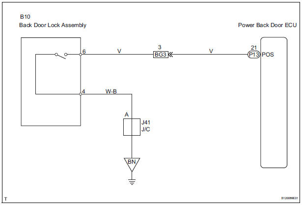
This DTC is output when a malfunction occurs in the position switch in the back door. This position switch detects if the back door is in the latch position and sends a position signal to the power back door ECU.
|
DTC No. |
DTC Detection Condition |
Trouble Area |
|
B2215 |
Back door does not operate |
|
WIRING DIAGRAM
INSPECTION PROCEDURE
1 CHECK WIRE HARNESS (BACK DOOR LOCK ASSEMBLY - POWER BACK DOOR ECU)
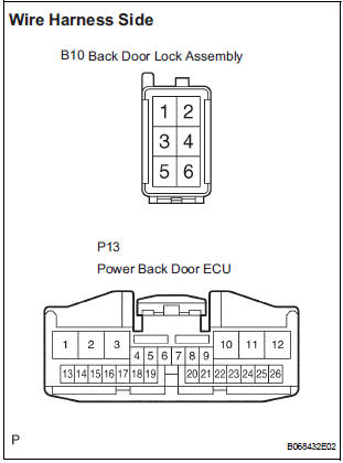
- Disconnect the B10 lock and P13 ECU connectors.
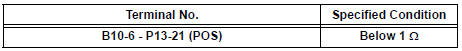
- Check the resistance between the wire harness side connectors.
Resistance (Check for open circuit)
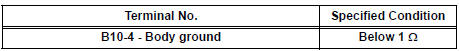
- Check the resistance between the B10 lock connector and body ground.
Resistance (Check for open circuit)
2 INSPECT BACK DOOR LOCK ASSEMBLY
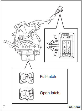
- Check operation of the door lock.
- Using a screwdriver, push the latch in order to put the back door lock in the locked condition (full-latch position).
- Connect the battery positive (+) lead to terminal 1
and the battery negative (-) lead to terminal 2. Then,
check operation of the latch.
OK: The latch turns to the open-latch position
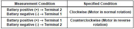
- Inspect motor operation when battery voltage is applied to the terminals.
OK
- Check the back door courtesy switch resistance.
- Check the resistance between the terminals of the courtesy switch.
Resistance
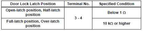
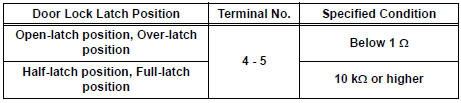
- Check the back door latch switch resistance.
- Check the resistance between the terminals of the latch switch.
Resistance
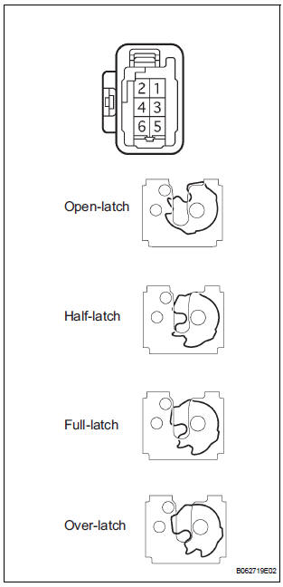
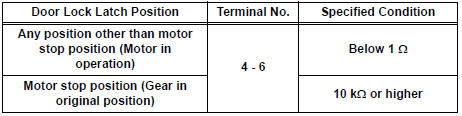
- Check the position switch resistance.
- Connect the battery positive (+) lead to connector terminal 1 and the negative (-) lead to connector terminal 2.
Resistance
REPLACE POWER BACK DOOR ECU
 Diagnostic trouble code chart
If a malfunction code is displayed during the DTC check,
check the circuit listed for that code in the table below.
(Proceed to the page given for that circuit.)
BACK DOOR CLOSER SYSTEM
...
 Back Door Closer does not Operate
DESCRIPTION
The power back door ECU controls the back door closer system. In response to
the signals output from
the switches related to the back door lock, the back door latch activates the
clo ...
Other materials:
Disassembly
1. REMOVE COOLER DRYER
(a) Using a hexagon wrench 14 mm (0.55 in.), remove
the cap from the modulator.
(b) Remove the O-ring from the cap.
(c) Using needle nose pliers, remove the cooler dryer. ...
Diagnostic trouble code chart
1. DTCS FOR OCCUPANT CLASSIFICATION SYSTEM
If a trouble code is displayed during the DTC check,
check the circuit listed for the code in the table below
(proceed to the page listed for that circuit).
HINT:
When DTC B1150/23 is detected as a result of
troubleshooting for the airbag system, pe ...
Road test
1. PROBLEM SYMPTOM CONFIRMATION
Inspect the SET function.
Turn the cruise control main switch on.
Drive at the required speed between 40 km/h
(25 mph) and 200 km/h (125 mph).
Push the cruise control main switch to -
(COAST)/SET.
After releasing t ...
