Toyota Sienna Service Manual: Laser sensor
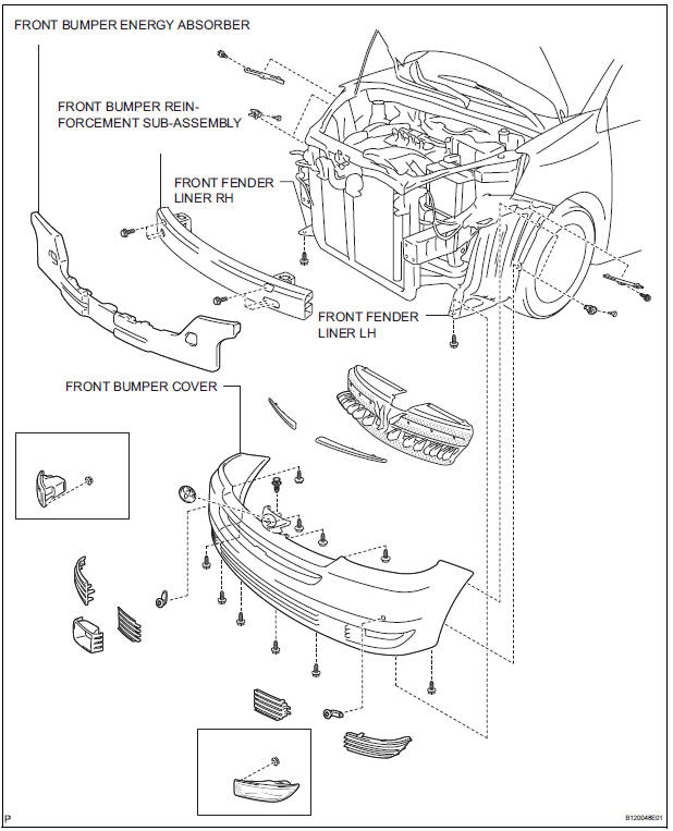
COMPONENTS
 Installation
1. INSTALL DISTANCE CONTROL ECU ASSEMBLY
Using a torque wrench, install the bolt.
Torque: 5 N*m (51 kgf*cm, 44 in.*lbf)
NOTICE:
Do not install the dropped or shocked distance
control ...
 Removal
1. REMOVE FRONT FENDER LINER LH
2. REMOVE FRONT FENDER LINER RH
3. REMOVE FRONT BUMPER COVER
4. REMOVE FRONT BUMPER ENERGY ABSORBER
5. REMOVE FRONT BUMPER REINFORCEMENT SUBASSEMBLY
6. REMOVE LASE ...
Other materials:
Memory recall function
Each electronic key can be registered to recall your preferred driving
position.
Registering procedure
Record your driving position to button “1” or “2” before performing
the following:
Carry only the key you want to register, and then close the driver’s
door.
If 2 or more keys ar ...
Inspection
1. INSPECT MULTIPLE DISC CLUTCH HUB
(a) Using a dial indicator, measure the inside diameter
of the forward clutch hub bushing
Standard inside diameter:
23.025 to 23.046 mm (0.9065 to 0.9073 in.)
Maximum inside diameter:
23.09 mm (0.9091 in.)
NOTICE:
Check the contact surface of ...
Initialization
1. RESET
When the control motor and clutch is replaced:
The power slide door ECU cannot receive a switch
signal from the control motor and clutch. This may
cause the power slide door system to enter fail-safe
mode and DTC (B2224 (LH) or B2223 (RH)) to set,
and also make the syste ...
