Toyota Sienna Service Manual: Mass or Volume Air Flow Circuit Range / Performance Problem
DTC P0101 Mass or Volume Air Flow Circuit Range / Performance Problem
DESCRIPTION
Refer to DTC P0100
|
DTC No. |
DTC Detection Condition |
Trouble Area |
|
P0101 |
|
MAF meter |
MONITOR DESCRIPTION
The MAF meter is a sensor that measures the amount of air flowing through the throttle valve. The ECM uses this information to determine the fuel injection time and to provide an appropriate air-fuel ratio.
Inside the MAF meter, there is a heated platinum wire which is exposed to the flow of intake air. By applying a specific electrical current to the wire, the ECM heats it to a specific temperature. The flow of incoming air cools both the wire and an internal thermistor, changing their resistance. To maintain a constant current value, the ECM varies the voltage applied to these components of the MAF meter. The voltage level is proportional to the air flow through the sensor, and the ECM uses it to calculate the intake air volume.
If there is a defect in the sensor, or an open or short in the circuit, the voltage level deviates from the normal operating range. The ECM interprets this deviation as a malfunction in the MAF meter and sets the DTC.
Example: If the voltage is more than 2.2 V, or less than 0.73 V while idling, the ECM determines that there is a malfunction in the MAF meter and sets the DTC.
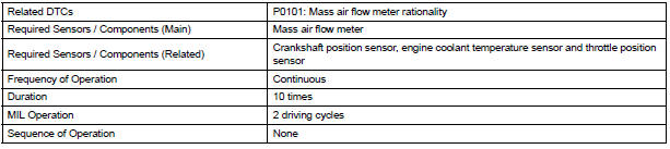
MONITOR STRATEGY
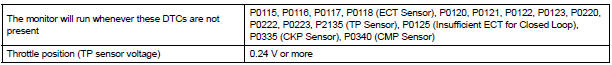
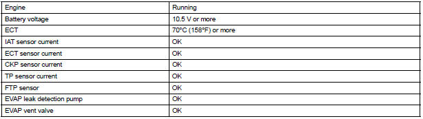
TYPICAL ENABLING CONDITIONS
TYPICAL MALFUNCTION THRESHOLDS

WIRING DIAGRAM
Refer to DTC P0100
INSPECTION PROCEDURE
HINT: Read freeze frame data using the intelligent tester. The ECM records vehicle and driving condition information as freeze frame data the moment a DTC is stored. When troubleshooting, freeze frame data can be helpful in determining whether the vehicle was running or stopped, whether the engine was warmed up or not, whether the air-fuel ratio was lean or rich, as well as other data recorded at the time of a malfunction
1 CHECK ANY OTHER DTCS OUTPUT (IN ADDITION TO DTC P0101)
- Connect the intelligent tester to the DLC3.
- Turn the ignition switch to the ON position.
- Turn the tester on.
- Select the following menu items: DIAGNOSIS / ENHANCED OBD II / DTC INFO / CURRENT CODES.
- Read the DTCs.
Result

HINT: If any DTCs other than P0101 are output, troubleshoot those DTCs first.
GO TO DTC CHART
 Mass or Volume Air Flow Circuit/ Mass or Volume Air Flow Circuit Low Input/
Mass or Volume Air Flow Circuit High Input
Mass or Volume Air Flow Circuit/ Mass or Volume Air Flow Circuit Low Input/
Mass or Volume Air Flow Circuit High Input
DESCRIPTION
The Mass Air Flow (MAF) meter is a sensor that measures the amount of air
flowing through the throttle
valve. The ECM uses this information to determine the fuel injection time and to ...
 Intake Air Temperature Circuit/ Intake Air Temperature Circuit Low Input/
Intake Air Temperature Circuit High Input
Intake Air Temperature Circuit/ Intake Air Temperature Circuit Low Input/
Intake Air Temperature Circuit High Input
DTC P0110 Intake Air Temperature Circuit
DTC P0112 Intake Air Temperature Circuit Low Input
DTC P0113 Intake Air Temperature Circuit High Input
DESCRIPTION
The Intake Air Temperature (IAT) sensor, ...
Other materials:
Passenger Airbag ON/OFF Indicator Circuit
Malfunction
DTC B1152/28 Passenger Airbag ON/OFF Indicator Circuit
Malfunction
DESCRIPTION
The passenger airbag ON/OFF indicator circuit consists of the center airbag
sensor assembly and
passenger airbag ON/OFF indicator.
This circuit indicates the operation condition of the front passenger airbag,
t ...
Power mirror control system (w/o Memory)
PARTS LOCATION
Problem symptoms table
POWER MIRROR CONTROL SYSTEM
Symptom
Suspected area
Mirror does not operate
Outer mirror switch assembly
Outer rear view mirror assembly
Wire harness
Mirror operates abnormally
O ...
GPS Receiver Error
DTC 58-11 GPS Receiver Error
DTC 80-11 GPS Receiver Error
DESCRIPTION
DTC No.
DTC Detection Condition
Trouble Area
58-11
RTC, ROM, and RAM of the GPS receiver and
TCXO error
GPS receiver is failed
Radio and navigation assembly ...
