Toyota Sienna Service Manual: No Answer-Back (Hazard Warning Light and Wireless Door Lock Buzzer)
DESCRIPTION If there is no answer-back of the hazard light signal and the wireless door lock buzzer although the wireless control function is operating normally, there might be a malfunction in the hazard light signal and the wireless door lock buzzer signal which are output from the multiplex network body ECU.
NOTICE: Troubleshooting should be started after confirming that the answer-back function has been switched ON through customization.
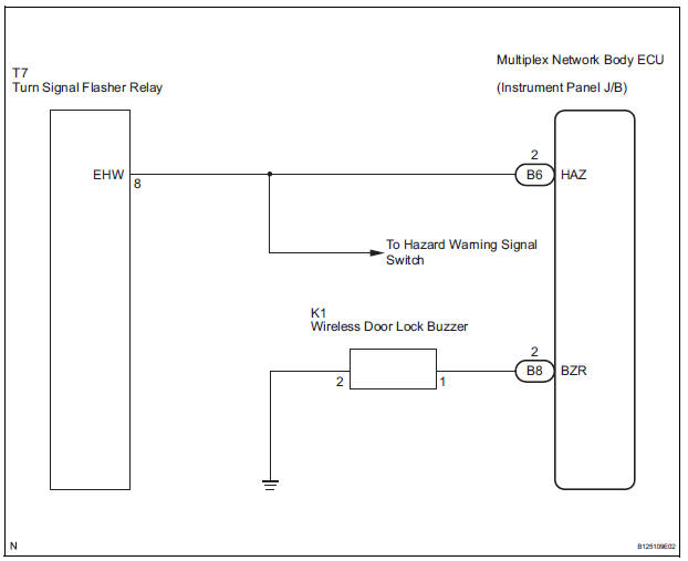
WIRING DIAGRAM
INSPECTION PROCEDURE
When using intelligent tester:
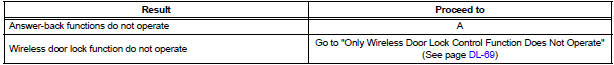
1 CHECK WIRELESS DOOR LOCK CONTROL SYSTEM
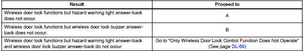
- Check whether the wireless door lock functions by operating the transmitter switch.
HINT: When the wireless door LOCK/UNLOCK operation can be performed, it means that the wireless signal from the transmitter is properly input to the multiplex network body ECU
Result
2 PERFORM ACTIVE TEST BY INTELLIGENT TESTER
- Connect the intelligent tester to the DLC3.
- Turn the ignition switch ON and push the intelligent tester main switch ON.
- Select the item "HAZARD" in the ACTIVE TEST and check the turn signal flasher relay ON/OFF.
- Select the item "BUZZ RESP SOUND" in the ACTIVE TEST and check the wireless buzzer ON/OFF
BODY:
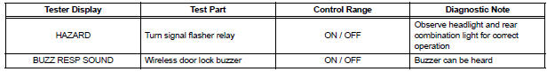
Result
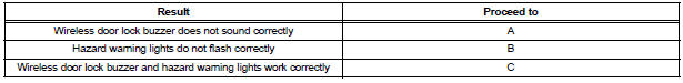
3 CHECK HAZARD WARNING LIGHTS
- Check that the hazard warning lights blink when the hazard warning signal switch is pressed.
REPLACE MULTIPLEX NETWORK BODY ECU
4 INSPECT WIRELESS DOOR LOCK BUZZER

- Check the buzzer resistance.
NOTICE:
- The buzzer circuit is built into the ECU, not into the buzzer itself.
- When battery voltage is directly applied to the buzzer, the buzzer does not sound.
- Check the resistance between terminals of the buzzer.
Standard
5 CHECK HARNESS AND CONNECTOR (WIRELESS DOOR LOCK BUZZER - MULTIPLEX NETWORK BODY ECU)
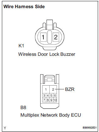
- Disconnect the K1 buzzer connector and B8 ECU connector.
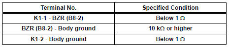
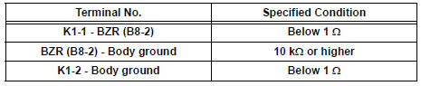
- Measure the resistance according to the value(s) in the table below.
Standard resistance
REPLACE MULTIPLEX NETWORK BODY ECU
When not using intelligent tester:
1 CHECK WIRELESS DOOR LOCK CONTROL SYSTEM
- Check whether the wireless door lock functions by operating the transmitter switch.
HINT: When the wireless door LOCK/UNLOCK operation can be performed, it means that the wireless signal from the transmitter is properly input to the multiplex network body ECU
Result
2 CHECK HAZARD WARNING LIGHTS
- Check that the hazard warning lights blink when the hazard warning signal switch is pressed.
REPLACE MULTIPLEX NETWORK BODY ECU
3 INSPECT WIRELESS DOOR LOCK BUZZER
- Check the buzzer resistance.
NOTICE:
- The buzzer circuit is built into the body ECU, not into the buzzer itself.
- When battery voltage is directly applied to the buzzer, the buzzer does not sound.
- Check the resistance between terminals of the buzzer.
Standard resistance
4 CHECK HARNESS AND CONNECTOR (WIRELESS DOOR LOCK BUZZER - MULTIPLEX NETWORK BODY ECU)
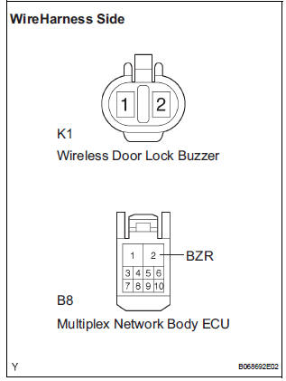
- Disconnect the K1 wireless buzzer connector and B8 ECU connector.
- Measure the resistance according to the value(s) in the table below.
Standard resistance
REPLACE MULTIPLEX NETWORK BODY ECU
 Wireless Door Lock Tuner Circuit Malfunction
DTC B1242 Wireless Door Lock Tuner Circuit Malfunction
DESCRIPTION
When a RDA signal is not input to the door control receiver within 1 second
after the multiplex network
body ECU outputs a PRG s ...
 Only Wireless Door Lock Control Function does not Operate
DESCRIPTION
The door control receiver receives a signal from the transmitter and sends
this signal to the multiplex
network body ECU. Then, the multiplex network body ECU controls operation of the ...
Other materials:
Disassembly
1. REMOVE RETURN TUBE NO.2
(a) Using SST, remove the return tube No. 2.
SST 09023-12701
2. REMOVE STEERING LEFT TURN PRESSURE TUBE
(a) Using SST, remove the left turn pressure tube.
SST 09023-38201
(b) Remove the 2 O-rings from the left turn pressure
tube.
3. REMOVE STEERING RIGH ...
Vehicle Speed Signal Circuit between Stereo Component Amplifier and
Combination Meter
DESCRIPTION
This circuit is necessary for the ASL (Auto Sound Leveliser) built into the
stereo component amplifier.
Speed signals are received from the combination meter and used for the ASL.
The ASL function automatically adjusts the sound data in order to enable hearing
the clear audio ...
Making a call
Once a Bluetooth® phone is registered, you can make a call
using the following procedure:
Dialing
Display the phone screen.
Select the ŌĆ£Dial PadŌĆØ tab and enter a phone number.
To delete the input phone number, select
.
For the first digit, you can enter ŌĆ£+ŌĆØ by selecting ŌĆ£&# ...
