Toyota Sienna Service Manual: Only Wireless Door Lock Control Function does not Operate
DESCRIPTION
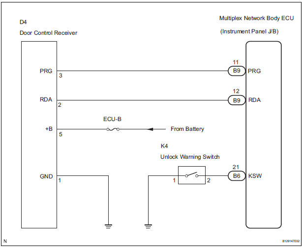
The door control receiver receives a signal from the transmitter and sends this signal to the multiplex network body ECU. Then, the multiplex network body ECU controls operation of the door locks and power windows.
Then, the power slide door ECU causes the power slide door to open or close when it receives a signal from the transmitter via the door control receiver and multiplex network body ECU. Also, the power back door ECU causes the power back door to open or close when it receives a signal from the transmitter via the door control receiver and multiplex network body ECU.
WIRING DIAGRAM
INSPECTION PROCEDURE
1 CHECK WIRELESS DOOR LOCK CONTROL SYSTEM
- Check the wireless door lock control system
2 REPLACE TRANSMITTER BATTERY
- After replacing the transmitter battery with a new or normal one, check that the doors can lock and unlock, using the transmitter LOCK/UNLOCK switch
3 CHECK WIRELESS DOOR LOCK (STANDARD OPERATION)
- Using the transmitter to LOCK/UNLOCK doors in standard operation, check that the doors can lock and unlock.
NOTICE: Standardized test procedure: Press the transmitter switch for 1 second, directing the beam to driver's door outside handle from a distance of 1 m (39.4 in.).
The transmitter should be pointed directly at the door handle, i.e at 90 angle to the vehicle body.
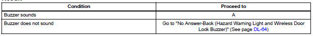
4 CHECK WIRELESS DOOR LOCK BUZZER
- Check that the wireless door lock buzzer sounds.
Result
5 SWITCH TO SELF DIAGNOSTIC MODE
- When using the intelligent tester: Switch to the self-diagnostic mode on the intelligent tester.
- Connect the intelligent tester to the DLC3.
- Turn the ignition switch ON and push the intelligent tester main switch ON.
HINT: Please refer to the intelligent tester operator's manual for further details.
- When not using the intelligent tester: Switch to the self-diagnostic mode by operating the ignition key cylinder.
- Insert the key into the ignition key cylinder and remove it under the initial vehicle condition.
- Within 5 seconds after the above step, insert the key into the ignition key cylinder and turn the ignition switch from ON to OFF once.
- ) Within 30 seconds after the above step, turn the ignition switch from ON to OFF 9 times.
NOTICE: If operation has failed, the system will return to the normal mode.
HINT:
- Operation of the ignition switch from OFF to ON will end the self-diagnostic mode.
- Do not lock or unlock doors during the selfdiagnostic mode.
- Check that the system has switched to self-diagnostic mode by the answer-back of the wireless door lock buzzer sound.
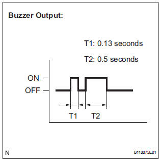
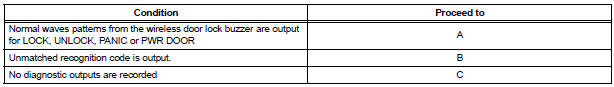
6 CHECK SELF DIAGNOSTIC MODE
- Inspect the diagnosis outputs when the door control transmitter switch is held down (The diagnosis outputs can be checked with the sound of the wireless door lock buzzer).
Result
7 REGISTER RECOGNITION CODE
- Check that the system can switch to rewrite mode or add mode and also check wether a recognition code can be registered.
END
8 CHECK DOOR CONTROL RECEIVER
- When a new or normal door control transmitter switch for the same type vehicle is held down, check that a diagnosis of unmatching recognition code is output
REPLACE DOOR CONTROL TRANSMITTER
9 REPLACE DOOR CONTROL RECEIVER
- Replace the door control receiver with normal one.
OK: The system returns to normal operation.
REPLACE DOOR CONTROL RECEIVER
10 CONFIRM SELF DIAGNOSTIC MODE
- When the input method for switching the system to selfdiagnostic mode is correct, proceed to A.
- When the input method for switching the system to selfdiagnostic mode is incorrect, proceed to B.
11 READ VALUE OF DATA LIST
- Using the intelligent tester, check the DATA LIST for proper functioning of the un-lock warning switch.
BODY (Multiplex network body ECU):

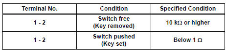
12 INSPECT UN-LOCK WARNING SWITCH ASSEMBLY
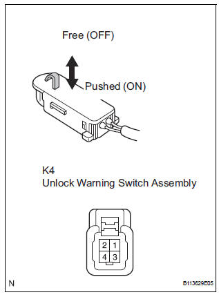
- Inspect the resistance of the un-lock warning switch
Standard resistance
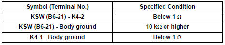
13 CHECK HARNESS AND CONNECTOR (MULTIPLEX NETWORK BODY ECU - UN-LOCK WARNING SWITCH)
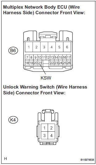
- Disconnect the B6 ECU connector and K4 switch connector.
- Measure the resistance according to the value(s) in the table below.
Standard resistance
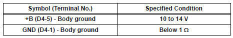
14 CHECK HARNESS AND CONNECTOR (DOOR CONTROL RECEIVER - BODY GROUND)
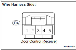
- Disconnect the D4 receiver connector.
- Measure the resistance according to the value(s) in the table below.
Standard
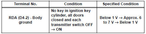
15 CHECK DOOR CONTROL RECEIVER (OUTPUT)
- Reconnect the D4 receiver connector.
- Measure the resistance according to the value(s) in the table below.
Standard
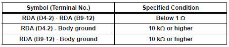
16 CHECK HARNESS AND CONNECTOR (MULTIPLEX NETWORK BODY ECU - DOOR CONTROL RECEIVER)
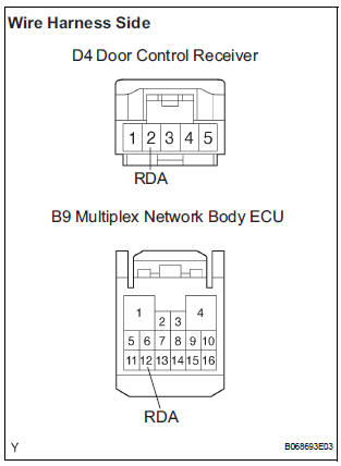
- Disconnect the D4 receiver connector and B9 ECU connector.
- Measure the resistance according to the value(s) in the table below.
Standard resistance
17 REPLACE DOOR CONTROL RECEIVER
- Replace the door control receiver with normal one.
OK: The system returns to normal operation.
18 REPLACE MULTIPLEX NETWORK BODY ECU
- Replace the multiplex network body ECU with normal one.
OK: The system returns to normal operation.
REPLACE MULTIPLEX NETWORK BODY ECU
 No Answer-Back (Hazard Warning Light and Wireless Door Lock
Buzzer)
No Answer-Back (Hazard Warning Light and Wireless Door Lock
Buzzer)
DESCRIPTION
If there is no answer-back of the hazard light signal and the wireless door lock
buzzer although the
wireless control function is operating normally, there might be a malfunction in
...
 Key reminder warning system
Parts location
System description
1. KEY REMINDER WARNING SYSTEM DESCRIPTION
When the driver side door is opened with the
ignition key in the ACC or LOCK position, this
system caus ...
Other materials:
Precaution
1. HANDLING PRECAUTION FOR CRUISE CONTROL
SYSTEM
Turn the cruise control main switch off when not
using the cruise control system.
Be careful as the vehicle speed increases when
driving downhill with the cruise control system on.
The + (ACCEL)/RES (RESUME) operation ch ...
On-vehicle inspection
1. INSPECT STEERING PAD (VEHICLE NOT INVOLVED IN COLLISION)
Perform a diagnostic system check.
With the steering pad installed on the vehicle,
perform a visual check. If there are any defects as
mentioned below, replace the steering pad with a
new one:
Cuts, minute cracks or ...
Installation
1. INSTALL RADIO NO. 2 BRACKET
Install radio No. 2 bracket with the 4 screws.
2. INSTALL RADIO NO. 1 BRACKET
Install radio No. 1 bracket with the 4 screws.
3. INSTALL RADIO RECEIVER
Connect the connector.
Install the radio receiver with the 4 scr ...
