Toyota Sienna Service Manual: Voice is not Recognized
INSPECTION PROCEDURE
1 CHECK NAVIGATION SETTINGS
- Enter the "Menu" screen by pressing the "MENU" switch.
- Select "Setup
- Check that "Voice Recognition Guidance" is not OFF.
OK: Voice Recognition Guidance is not OFF.
2 CHECK MAP DISC
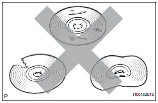
- Check that the map disc is not deformed or cracked.
OK: No deformations or cracks on map disc.
3 CHECK MAP DISC
- Check for dirt on the map disc surface.
OK: No dirt is on the map disc surface.
NOTICE: Do not use a conventional record cleaner or antistatic preservative.
HINT: If the disc is dirty, clean the disc by wiping the disc's surface radially with a soft cloth.
4 CHECK MICROPHONE (NAVIGATION CHECK MODE)
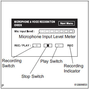
- Enter the "MICROPHONE & VOICE RECOGNITION CHECK" mode.
- When voice is input into the microphone, check that the microphone input level meter changes according to the input voice.
- Push the recording switch and perform voice recording.
HINT: Voice can be recorded up to 5 seconds.
- Check that the recording indicator remains on while recording and that the recorded voice is played normally without noise or distortion.
OK: All check results are normal.
REPLACE RADIO AND NAVIGATION ASSEMBLY
 Voice Recognition Difficulty
INSPECTION PROCEDURE
1 CHECK CONDITION
Check if the system's voice recognition level is low by
using only one particular voice.
OK:
System's voice recognition level is low with any
voice.
...
 Cellular Phone Registration Failure, Phone Directory Transfer Failure
INSPECTION PROCEDURE
1 CHECK CURRENT CONDITIONS
Proceed to the next step according to the table below.
RESULT
2 CHECK USING ANOTHER CELLULAR PHONE
Check if the system functions using an ...
Other materials:
Disassembly
1. REMOVE TRANSFER COVER GASKET
(a) Remove the transfer gasket from the transfer
assembly.
2. REMOVE TRANSFER CASE BREATHER PLUG
(a) Using a screwdriver and a hammer, remove the
transfer case breather plug from the No. 1 transfer
case cover.
NOTICE:
Be careful not to damage the conta ...
Disposal
HINT:
On the RH side, use the same procedures as on the LH side.
1. DISPOSE OF BACK DOOR STAY SUB-ASSEMBLY LH
Horizontally fix the stay in a vise with the piston-rod
pulled out.
Wearing safety glasses, gradually cut a part
between A and B as shown in the illustration using a
metal ...
Diagnosis system
1. DESCRIPTION
Front power seat control system data can be read
through the Data Link Connector 3 (DLC3) of the
vehicle. When the system seems to be
malfunctioning, use the intelligent tester to check for
malfunctions and perform repairs.
2. CHECK DLC3
The vehicle us ...
