Toyota Sienna Service Manual: On-vehicle inspection
1. INSPECT BACK WINDOW (DEFOGGER WIRE)
NOTICE:
- When cleaning the glass, wipe the glass along the wire using a soft and dry cloth. Take care not to damage the wires.
- Do not use detergents or glass cleaners including abrasive ingredients.
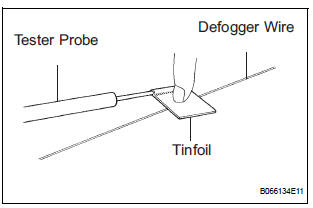
- When measuring voltage, wrap a piece of tin foil around the tip of the negative probe and press the foil against the wire with your finger, as shown in the illustration.

- Turn the ignition switch ON.
- Turn the defogger switch ON.
- Inspect the voltage at the center of each defogger wire, as shown in the illustration.
Standard voltage
HINT: If there is approximately 10 V, the wire may be broken between the center of the wire and the end on the battery side. If there is no voltage, the wire may be broken between the center of the wire and the end on the ground side.
- Place the voltmeter positive (+) lead against the defogger wire on the battery side.
- Place the voltmeter negative (-) lead with the foil strip against the wire on the ground side.
- Slide the positive (+) lead from the battery side to the ground side.
- The point where the voltmeter deflects from approx 10 V to 0 V is the place where the defogger wire is broken.
HINT: If the defogger wire is not broken, the voltmeter indicates 0 V at the positive (+) end of the defogger wire but gradually increases to about 12 V as the meter probe moves to the other end.
2. INSPECT WIRE HARNESS (FRONT WINDOW DEICER WIRE)
- Inspect the resistance of the deicer wire.
Standard resistance
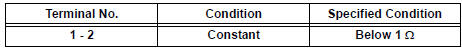
If the result is not as specified, replace the window.
 Problem symptoms table
WINDOW DEFOGGER SYSTEM
Symptom
Suspected area
w/ Deicer: Front window deicer does not operate.
(indicator light ON)
FR DEF fuse
Front window deicer re ...
 Repair
1. REPAIR REAR WINDOW DEFOGGER WIRE
Clean the broken wire tips with grease, wax and
silicone remover.
Place the masking tape along the both sides of the
wire.
Thoroug ...
Other materials:
Symptom simulation
HINT:
The most difficult case in troubleshooting is when no
problem symptoms occur. In such a case, a thorough
problem analysis must be carried out. A simulation of the
same or similar conditions and environment in which the
problem occurred in the customer's vehicle should be
carried out. No ...
Battery
Check the battery as follows:
Battery exterior
Make sure that the battery terminals are not corroded and that
there are no loose connections, cracks, or loose clamps.
Terminals
Hold-down clamp
Before recharging
When recharging, the battery produces hydrogen gas which is flammable an ...
Do-it-yourself service
precautions
If you perform maintenance yourself, be sure to follow the correct
procedure as given in these sections.
Items
Parts and tools
Battery condition
Warm water
Baking soda
Grease
Conventional wrench (for terminal clamp bolts)
Brake ...
