Toyota Sienna Service Manual: Symptom simulation
HINT:
The most difficult case in troubleshooting is when no problem symptoms occur. In such a case, a thorough problem analysis must be carried out. A simulation of the same or similar conditions and environment in which the problem occurred in the customer's vehicle should be carried out. No matter how much skill or experience a technician has, troubleshooting without confirming the problem symptoms will lead to important repairs being overlooked and mistakes or delays.
For example:
With a problem that only occurs when the engine is cold or as a result of vibration caused by the road during driving, the problem can never be determined if the symptoms are being checked on a stationary vehicle or a vehicle with a warmed-up engine. Vibration, heat or water penetration (moisture) is difficult to reproduce. The symptom simulation tests below are effective substitutes for the conditions and can be applied on a stationary vehicle. Important points in the symptom simulation test: In the symptom simulation test, the problem symptoms as well as the problem area or parts must be confirmed. First, narrow down the possible problem circuits according to the symptoms. Then, connect the tester and carry out the symptom simulation test, judging whether the circuit being tested is defective or normal. Also, confirm the problem symptoms at the same time.
Refer to the problem symptoms table for each system to narrow down the possible causes.
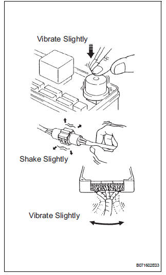
(a) VIBRATION METHOD: When a malfunction seems to occur as a result of vibration.
(1) PART AND SENSOR
Apply slight vibration with a finger to the part of the sensor suspected to be the cause of the problem, and check whether or not the malfunction occurs.
| NOTICE: Applying strong vibration to relays may open relays. |
(2) CONNECTORS
Slightly shake the connector vertically and horizontally.
(3) WIRE HARNESS
Slightly shake the wire harness vertically and horizontally.
HINT:
The connector joint and fulcrum of the vibration are the major areas that should be checked thoroughly.
(b) HEAT METHOD: When a malfunction seems to occur when the area in question is heated.
(1) Heat the component that is the possible cause of the malfunction with a hair dryer or similar device. Check if the malfunction occurs.
NOTICE:
|
(c) WATER SPRINKLING METHOD: When a malfunction seems to occur on a rainy day or in high-humidity.
(1) Sprinkle water onto the vehicle and check if the malfunction occurs.
NOTICE:
|
HINT:
If the vehicle has or had a water leakage problem, the leakage may have damaged the ECU or connections. Look for evidence of corrosion or short circuits. Proceed with caution during water tests.
(d) HIGH ELECTRICAL LOAD METHOD: When a malfunction seems to occur when electrical load is excessive.
(1) Turn on the heater blower, headlight, rear window defogger and all other electrical loads.
Check if the malfunction reoccurs.
 Symptom confirmation and diagnostic trouble code
HINT:
The diagnostic system in the SIENNA has various
functions.
The first function is the Diagnostic Trouble Code
(DTC) check. A DTC is a code stored in the ECU
memory whenever a malfunctio ...
 Diagnostic trouble code chart
Look for output Diagnostic Trouble Codes (DTCs) (from the
DTC checks) in the appropriate section's Diagnostic Trouble
Code Chart. Use the chart to determine the trouble area and
the proper inspecti ...
Other materials:
Data list / active test
1. DATA LIST
HINT:
Using the intelligent tester to read the DATA LIST allows
the values or states of switches, sensor, actuators and
other items to be read without removing any parts. This
non-intrusive inspection can be very useful because
intermittent conditions or signals may be discovered
...
Engine oil pressure switch
ON-VEHICLE INSPECTION
1. INSPECT ENGINE OIL PRESSURE SWITCH
ASSEMBLY
Disconnect the connector from the oil pressure
switch assembly.
With the switch still installed, measure the
resistance between the terminal of the engine oil
pressure switch and engine ground.
Standard ...
Installation
1. Install purge vsv
(A) install the purge vsv with the bolt.
Torque: 10 n*m (102 kgf*cm, 7 ft.*Lbf)
(B) connect the 2 vacuum hoses and no. 1 Vacuum
switching valve connector.
2. INSTALL V-BANK COVER SUB-ASSEMBLY (See
page EM-63)
3. CONNECT CABLE TO NEGATIVE BATTERY
TERMINAL ...
