Toyota Sienna Service Manual: Open in Front Pretensioner Squib LH Circuit
DTC B0136/74 Open in Front Pretensioner Squib LH Circuit
DESCRIPTION
The front pretensioner squib LH circuit consists of the center airbag sensor assembly and the front seat outer belt assembly LH.
This circuit instructs the SRS to deploy when deployment conditions are met.
DTC B0136/74 is recorded when an open circuit is detected in the front pretensioner squib LH circuit.
|
DTC No. |
DTC Detecting Condition |
Trouble Area |
|
B0136/74 |
|
|
INSPECTION PROCEDURE
HINT:
- Perform the simulation method by selecting the "check mode" (signal check) with the intelligent tester (8).
- After selecting the "check mode" (signal check), perform the simulation method by wiggling each connector of the airbag system or driving the vehicle on a city or rough road
1 CHECK FRONT SEAT OUTER BELT ASSEMBLY LH (FRONT PRETENSIONER SQUIB LH)
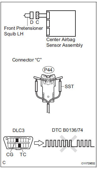
- Turn the ignition switch to the LOCK position.
- Disconnect the negative (-) terminal cable from the battery, and wait for at least 90 seconds.
- Disconnect the connectors from the front seat outer belt assembly LH.
- Connect the white wire side of SST (resistance 2.1 Ω) to the floor wire.
CAUTION: Never connect a tester to the front seat outer belt assembly LH (front pretensioner squib LH) for measurement, as this may lead to a serious injury due to airbag deployment.
NOTICE: Do not forcibly insert the SST into the terminals of the connector when connecting.
Insert the SST straight into the terminals of the connector.
SST 09843-18060
- Connect the negative (-) terminal cable to the battery, and wait for at least 2 seconds.
- Turn the ignition switch to the ON position, and wait for at least 60 seconds.
- Clear the DTCs stored in memory (5).
- Turn the ignition switch to the LOCK position.
- Turn the ignition switch to the ON position, and wait for at least 60 seconds.
- Check the DTCs
OK: DTC B0136/74 is not output.
HINT: Codes other than DTC B0136/74 may be output at this time, but they are not related to this check.
 Go to step 2

REPLACE FRONT SEAT OUTER BELT ASSEMBLY LH
2 CHECK FLOOR WIRE (FRONT PRETENSIONER SQUIB LH CIRCUIT)
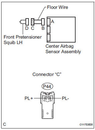
- Turn the ignition switch to the LOCK position.
- Disconnect the negative (-) terminal cable from the battery, and wait for at least 90 seconds.
- Disconnect the SST (resistance 2.1 Ω) from the floor wire.
- Disconnect the connector from the center airbag sensor assembly.
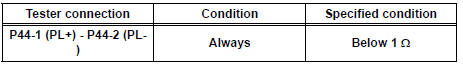
- Measure the resistance according to the value(s) in the table below.
Standard resistance
REPAIR OR REPLACE FLOOR WIRE
3 CHECK CENTER AIRBAG SENSOR ASSEMBLY
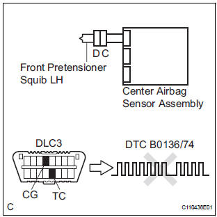
- Connect the connectors to the front seat outer belt assembly LH and the center airbag sensor assembly.
- Connect the negative (-) terminal cable to the battery, and wait for at least 2 seconds.
- Turn the ignition switch to the ON position, and wait for at least 60 seconds.
- Clear the DTCs stored in memory (5).
- Turn the ignition switch to the LOCK position.
- Turn the ignition switch to the ON position, and wait for at least 60 seconds.
- Check the DTCs (5).
OK: DTC B0136/74 is not output. HINT: Codes other than DTC B0136/74 may be output at this time, but they are not related to this check.
 REPLACE CENTER AIRBAG SENSOR
ASSEMBLY
REPLACE CENTER AIRBAG SENSOR
ASSEMBLY

USE SIMULATION METHOD TO CHECK
 Short in Front Pretensioner Squib LH Circuit
DTC B0135/73 Short in Front Pretensioner Squib LH Circuit
DESCRIPTION
The front pretensioner squib LH circuit consists of the center airbag sensor
assembly and the front seat
outer belt assembly ...
 Short to GND in Front Pretensioner Squib LH
Circuit
Short to GND in Front Pretensioner Squib LH
Circuit
DTC B0137/71 Short to GND in Front Pretensioner Squib LH
Circuit
DESCRIPTION
The front pretensioner squib LH circuit consists of the center airbag sensor
assembly and the front seat
outer belt a ...
Other materials:
Wireless remote control
Vehicles without a smart key system (type A)
Locks all doors
Unlocks all doors
Sounds the alarm
Vehicles without a smart key system (type B)
Locks all doors
Unlocks all doors
Opens and closes the left side power sliding door
Opens and closes the right sid ...
Rear Blower Motor Circuit
DESCRIPTION
Power to the rear blower motor is supplied from the battery via the RR A/C
relay.
The rear blower motor speed level varies between 0 and 31 based on the voltage
difference measured
between the terminals of the motor.
The voltage difference measured between the terminals of th ...
Reassembly
1. INSTALL FRONT DISC
(a) Aligning the matchmarks, install the front disc.
HINT:
Select the installation position where the disc has
the minimum runout.
2. INSPECT DISC RUNOUT
(a) Temporarily fasten the disc with the hub nuts.
Torque: 103 N*m (1,050 kgf*cm, 76 ft.*lbf)
(b) Using a ...
