Toyota Sienna Service Manual: Definition of terms
|
Terms |
Definitions |
| Monitor Description | Description of what ECM monitors and how to detect malfunctions (monitoring purpose and details). |
| Related DTCs | A group of diagnostic trouble codes that are output by ECM based on the same malfunction detection logic. |
| Typical Enabling Conditions | Preconditions that allow ECM to detect malfunction.
With all preconditions satisfied, ECM sets DTC when monitored value(s) exceeds malfunction threshold(s). |
| Sequence of Operation | Order of monitor priority, applied if multiple sensors and
components are involved in single malfunction detection
process.
Each sensor and component monitored in turn and not monitored until previous detection operation is completed. |
| Required Sensors / Components | Sensors and components used by ECM to detect each malfunction. |
| Frequency of Operation | Number of times ECM checks for each malfunction during each driving
cycle.
"Once per driving cycle" means ECM performs checks for that malfunction only once in single driving cycle. "Continuous" means ECM performs checks for that malfunction whenever enabling conditions are met. |
| Duration | Minimum time for which ECM must detect continuous deviation in monitored value(s) in order to set DTC. Timing begins when typical enabling conditions are met. |
| Malfunction Thresholds | Values, beyond which, ECM determines malfunctions exist and sets DTCs. |
| MIL Operation | Timing of MIL illumination after defect is detected.
"Immediate" means ECM illuminates MIL as soon as malfunction is detected. "2 driving cycles" means ECM illuminates MIL if the same malfunction is detected twice during the next sequential driving cycle. |
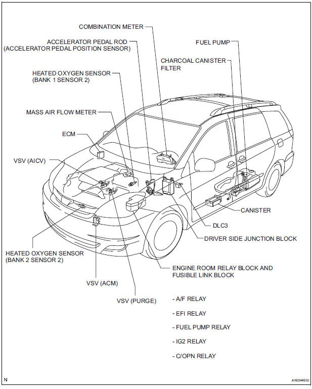
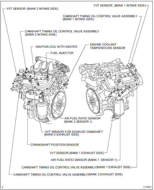
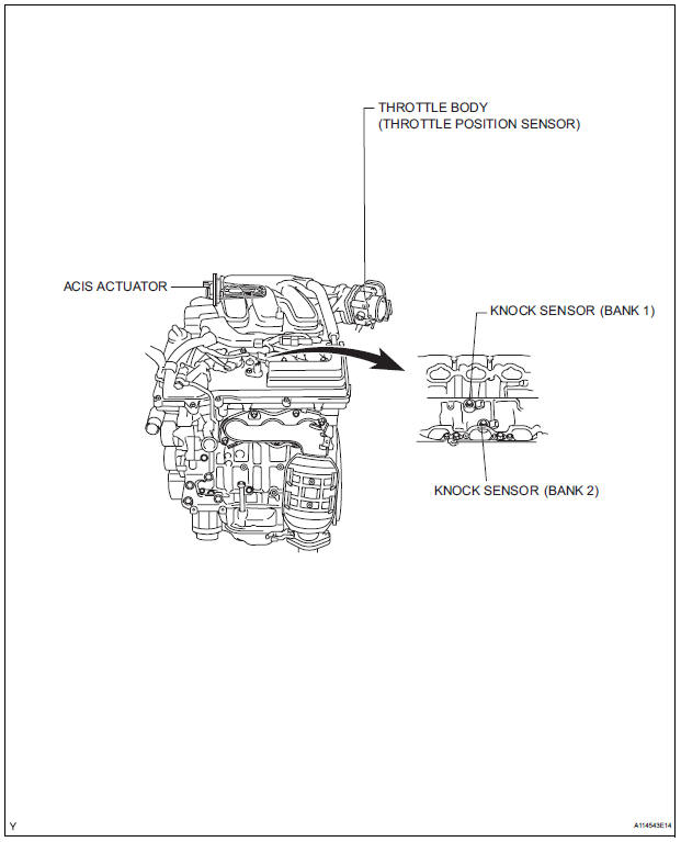
PARTS LOCATION
 Precaution
1. INITIALIZATION
NOTICE:
Perform RESET MEMORY (AT initialization) when
replacing the automatic transaxle assembly, engine
assembly or ECM (See page AX-16).
Perform REGISTRATIO ...
 System diagram
...
Other materials:
Installation
1. INSTALL SPIRAL CABLE
Check that the front wheels are facing straight
ahead.
Set the turn signal switch to the neutral position.
NOTICE:
If it is not in the neutral position, the pin of the
turn signal switch may snap.
Install the spiral cable.
NOTICE:
When ...
Inspection
1. INSPECT THERMOSTAT
(a) Inspect the thermostat.
HINT:
The valve opening temperature is inscribed on the
thermostat.
(b) Immerse the thermostat in water and gradually heat
the water.
(c) Check the valve opening temperature.
Valve opening temperature:
80 to 84°C (176 to 183°F) ...
Installation
1. INSTALL FRONT SEAT ASSEMBLY RH
Place the seat assembly in the cabin.
NOTICE:
Be careful not to damage the body.
Connect the connectors under the seat assembly.
Tighten the 2 bolts on the front side of the seat
assembly.
Torque: 37 N*m (375 kgf*cm, 27 ft.*lbf)
...
