Toyota Sienna Service Manual: Short to GND in Front Pretensioner Squib LH Circuit
DTC B0137/71 Short to GND in Front Pretensioner Squib LH Circuit
DESCRIPTION
The front pretensioner squib LH circuit consists of the center airbag sensor assembly and the front seat outer belt assembly LH.
This circuit instructs the SRS to deploy when deployment conditions are met.
DTC B0137/71 is recorded when a short to ground is detected in the front pretensioner squib LH circuit
|
DTC No. |
DTC Detecting Condition |
Trouble Area |
|
B0137/71 |
|
|
INSPECTION PROCEDURE
HINT:
- Perform the simulation method by selecting the "check mode" (signal check) with the intelligent tester (8).
- After selecting the "check mode" (signal check), perform the simulation method by wiggling each connector of the airbag system or driving the vehicle on a city or rough road
1 CHECK FRONT SEAT OUTER BELT ASSEMBLY LH (FRONT PRETENSIONER SQUIB LH)
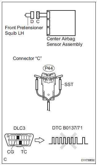
- Turn the ignition switch to the LOCK position.
- Disconnect the negative (-) terminal cable from the battery, and wait for at least 90 seconds.
- Disconnect the connectors from the front seat outer belt assembly LH.
- Connect the white wire side of SST (resistance 2.1 Ω) to the floor wire.
CAUTION: Never connect a tester to the front seat outer belt assembly LH (front pretensioner squib LH) for measurement, as this may lead to a serious injury due to airbag deployment.
NOTICE: Do not forcibly insert the SST into the terminals of the connector when connecting.
Insert the SST straight into the terminals of the connector.
SST 09843-18060
- Connect the negative (-) terminal cable to the battery, and wait for at least 2 seconds.
- Turn the ignition switch to the ON position, and wait for at least 60 seconds.
- Clear the DTCs stored in memory (5).
- Turn the ignition switch to the LOCK position.
- Turn the ignition switch to the ON position, and wait for at least 60 seconds.
- Check the DTCs (5).
OK: DTC B0137/71 is not output. HINT: Codes other than DTC B0137/71 may be output at this time, but they are not related to this check.
 Go to step 2

REPLACE FRONT SEAT OUTER BELT ASSEMBLY LH
2 FLOOR WIRE (FRONT PRETENSIONER SQUIB LH CIRCUIT)
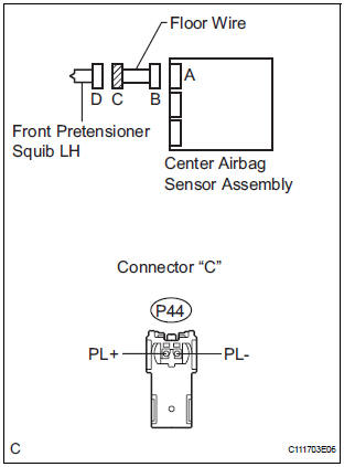
- Turn the ignition switch to the LOCK position.
- Disconnect the negative (-) terminal cable from the battery, and wait for at least 90 seconds.
- Disconnect the SST (resistance 2.1 Ω) from the floor wire.
- Disconnect the connector from the center airbag sensor assembly.
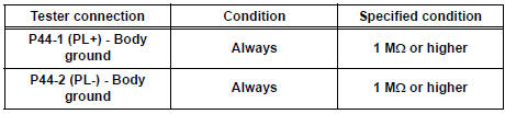
- Measure the resistance according to the value(s) in the table below.
Standard resistance
 REPAIR OR REPLACE FLOOR WIRE

3 CHECK CENTER AIRBAG SENSOR ASSEMBLY
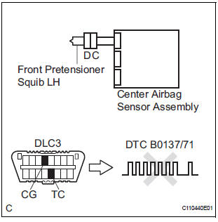
- Connect the connectors to the front seat outer belt assembly LH and the center airbag sensor assembly.
- Connect the negative (-) terminal cable to the battery, and wait for at least 2 seconds.
- Turn the ignition switch to the ON position, and wait for at least 60 seconds.
- Clear the DTCs stored in memory (5).
- Turn the ignition switch to the LOCK position.
- Turn the ignition switch to the ON position, and ait for at least 60 seconds.
- Check the DTCs (5).
OK: DTC B0137/71 is not output. HINT: Codes other than DTC B0137/71 may be output at this time, but they are not related to this check.
 REPLACE CENTER AIRBAG SENSOR
ASSEMBLY
REPLACE CENTER AIRBAG SENSOR
ASSEMBLY

USE SIMULATION METHOD TO CHECK
 Open in Front Pretensioner Squib LH Circuit
DTC B0136/74 Open in Front Pretensioner Squib LH Circuit
DESCRIPTION
The front pretensioner squib LH circuit consists of the center airbag sensor
assembly and the front seat
outer belt assembly L ...
 Short to B+ in Front Pretensioner Squib LH Circuit
DTC B0138/72 Short to B+ in Front Pretensioner Squib LH Circuit
DESCRIPTION
The front pretensioner squib LH circuit consists of the center airbag sensor
assembly and the front seat
outer belt ass ...
Other materials:
Mass or Volume Air Flow Circuit Range / Performance Problem
DESCRIPTION
Refer to DTC P0100 (See page ES-116).
MONITOR DESCRIPTION
The MAF meter is a sensor that measures the amount of air flowing through the
throttle valve. The ECM
uses this information to determine the fuel injection time and to provide an
appropriate air-fuel ratio.
Insi ...
Replacing light bulbs
Headlight low beams (halogen bulb)
For left side only: Open the fuse box cover.
Unplug the connector while
pushing the lock release.
Turn the bulb base counterclockwise.
Install a new light bulb.
Align the 3 tabs on the light bulb
with the mounting, and insert.
...
Opening the back door from outside the vehicle
Back door opener
Raise the back door while
pressing the back door opener
to release the lock to open the
back door.
Wireless remote control (vehicles with power back door)
Press and hold the switch to open/close the power back door
Vehicles without a smart key
system
Vehicl ...
