Toyota Sienna Service Manual: Open in Rear Curtain Shield Squib RH Circuit
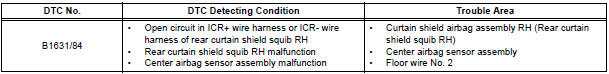
DTC B1631/84 Open in Rear Curtain Shield Squib RH Circuit
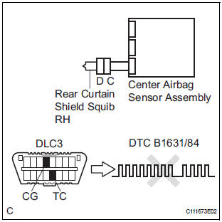
DESCRIPTION
The rear curtain shield squib RH circuit consists of the center airbag sensor assembly and the curtain shield airbag assembly RH.
The circuit instructs the SRS to deploy when deployment conditions are met.
DTC B1631/84 is recorded when an open circuit is detected in the rear curtain shield squib RH circuit.
WIRING DIAGRAM
INSPECTION PROCEDURE
HINT:
- Perform the simulation method by selecting the "check mode" (signal check) with the intelligent tester.
- After selecting the "check mode" (signal check), perform the simulation method by wiggling each connector of the airbag system or driving the vehicle on a city or rough road
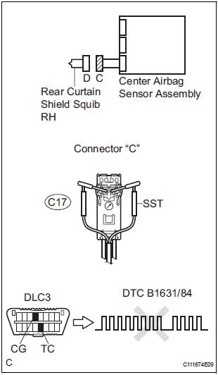
1 CHECK CURTAIN SHIELD AIRBAG ASSEMBLY RH (REAR CURTAIN SHIELD SQUIB RH)
- Turn the ignition switch to the LOCK position.
- Disconnect the negative (-) terminal cable from the battery, and wait for at least 90 seconds.
- Disconnect the connectors from the curtain shield airbag assembly RH.
- Connect the white wire side of SST (resistance 2.1 Ω) to
the floor wire No. 2.
CAUTION: Never connect a tester to the curtain shield airbag assembly RH (Rear curtain shield squib RH) for measurement, as this may lead to a serious injury due to airbag deployment.
NOTICE: Do not forcibly insert the SST into the terminals of the connector when connecting.
Insert the SST straight into the terminals of the connector.
SST 09843-18060
- Connect the negative (-) terminal cable to the battery, and wait for at least 2 seconds.
- Turn the ignition switch to the ON position, and wait for at least 60 seconds.
- Clear the DTCs stored in memory.
- Turn the ignition switch to the LOCK position.
- Turn the ignition switch to the ON position, and wait for at least 60 seconds.
- Check the DTCs
OK: DTC B1631/84 is not output.
HINT: Codes other than DTC B1631/84 may be output at this time, but they are not related to this check.
REPLACE CURTAIN SHIELD AIRBAG ASSEMBLY RH
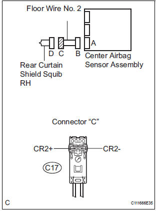
2 CHECK FLOOR WIRE NO.2 (REAR CURTAIN SHIELD SQUIB RH CIRCUIT)
- Turn the ignition switch to the LOCK position.
- Disconnect the negative (-) terminal cable from the battery, and wait for at least 90 seconds.
- Disconnect the SST (resistance 2.1 Ω) from the floor wire No. 2.
- Disconnect the connector from the center airbag sensor assembly.
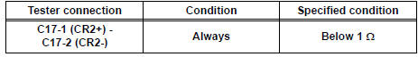
- Measure the resistance according to the value(s) in the table below.
Standard resistance
3 CHECK CENTER AIRBAG SENSOR ASSEMBLY
- Connect the connectors to the curtain shield airbag assembly RH and the center airbag sensor assembly.
- Connect the negative (-) terminal cable to the battery, and wait for at least 2 seconds.
- Turn the ignition switch to the ON position, and wait for at least 60 seconds.
- Clear the DTCs stored in memory.
- Turn the ignition switch to the LOCK position.
- Turn the ignition switch to the ON position, and wait for at least 60 seconds.
- Check the DTCs.
OK: DTC B1631/84 is not output.
HINT: Codes other than DTC B1631/84 may be output at this time, but they are not related to this check.
USE SIMULATION METHOD TO CHECK
 Short in Rear Curtain Shield Squib RH Circuit
DTC B1630/83 Short in Rear Curtain Shield Squib RH Circuit
DESCRIPTION
The rear curtain shield squib RH circuit consists of the center airbag sensor
assembly and the curtain
shield airbag assembl ...
 Short to GND in Rear Curtain Shield Squib RH
Circuit
Short to GND in Rear Curtain Shield Squib RH
Circuit
DTC B1632/81 Short to GND in Rear Curtain Shield Squib RH
Circuit
DESCRIPTION
The rear curtain shield squib RH circuit consists of the center airbag sensor
assembly and the curtain
shield airbag ...
Other materials:
Meter Illumination is Always Dark
DESCRIPTION
Confirm that the vehicle is equipped with the optitron meter, then
check this circuit.
The combination meter assembly receives a auto dimmer signal from the
body ECU by the multiplex
communication line.
WIRING DIAGRAM
INSPECTION PROCEDURE
1 CHECK MULTIPLEX CO ...
Diagnosis system
1. CHECK BATTERY VOLTAGE
Standard voltage:
11 to 14 V
If the voltage is below 11 V, recharge the battery before
proceeding.
2. CHECK DLC3
(a) The ECU uses the ISO 15765-4 for communication
protocol. The terminal arrangement of the DLC3
complies with SAE J1962 and matches the ISO
15765-4 f ...
Sliding door child-protector locks
The sliding door cannot be
opened by the inside door handle
and the second seat sliding door
switch when the lock is set.
Unlock
Lock
These locks can be set to prevent
children from opening the sliding
doors. Push down on each sliding
door switch to lock that sliding
door.
The p ...
