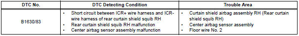
Toyota Sienna Service Manual: Short in Rear Curtain Shield Squib RH Circuit
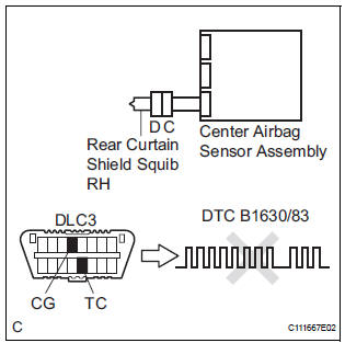
DTC B1630/83 Short in Rear Curtain Shield Squib RH Circuit
DESCRIPTION
The rear curtain shield squib RH circuit consists of the center airbag sensor assembly and the curtain shield airbag assembly RH.
The circuit instructs the SRS to deploy when deployment conditions are met.
DTC B1630/83 is recorded when a short circuit is detected in the rear curtain shield squib RH circuit.
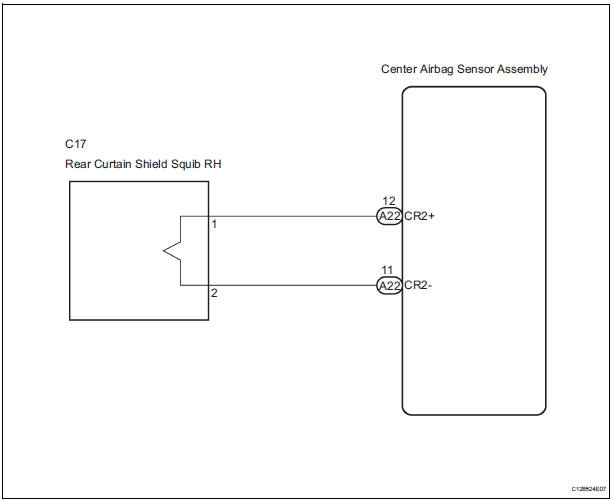
WIRING DIAGRAM
INSPECTION PROCEDURE
HINT:
- Perform the simulation method by selecting the "check mode" (signal check) with the intelligent tester
- After selecting the "check mode" (signal check), perform the simulation method by wiggling each connector of the airbag system or driving the vehicle on a city or rough road
1 CHECK CURTAIN SHIELD AIRBAG ASSEMBLY RH (REAR CURTAIN SHIELD SQUIB RH)
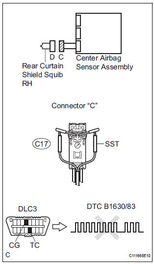
- Turn the ignition switch to the LOCK position.
- Disconnect the negative (-) terminal cable from the battery, and wait for at least 90 seconds.
- Disconnect the connectors from the curtain shield airbag assembly RH.
- Connect the white wire side of SST (resistance 2.1 Ω) to
the floor wire No. 2.
CAUTION: Never connect a tester to the curtain shield airbag assembly RH (Rear curtain shield squib RH) for measurement, as this may lead to a serious injury due to airbag deployment.
NOTICE: Do not forcibly insert the SST into the terminals of the connector when connecting.
Insert the SST straight into the terminals of the connector.
SST 09843-18060
- Connect the negative (-) terminal cable to the battery, and wait for at least 2 seconds.
- Turn the ignition switch to the ON position, and wait for at least 60 seconds.
- Clear the DTCs stored in memory.
- Turn the ignition switch to the LOCK position.
- Turn the ignition switch to the ON position, and wait for at least 60 seconds.
- Check the DTCs.
OK: DTC B1630/83 is not output.
HINT: Codes other than DTC B1630/83 may be output at this time, but they are not related to this check.
REPLACE CURTAIN SHIELD AIRBAG ASSEMBLY RH
2 CHECK CONNECTORS
- Turn the ignition switch to the LOCK position.
- Disconnect the negative (-) terminal cable from the battery, and wait for at least 90 seconds.
- Disconnect the SST (resistance 2.1 Ω) from the floor wire No. 2.
- Check that the floor wire No. 2 connectors (on the curtain shield airbag assembly RH side) are not damaged.
OK: The lock button is not disengaged, and the claw of the lock is not deformed or damaged.
3 CHECK FLOOR WIRE NO.2 (REAR CURTAIN SHIELD SQUIB RH CIRCUIT)
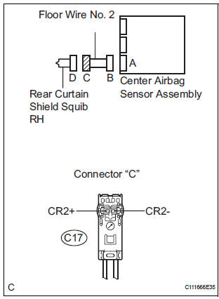
- Disconnect the connector from the center airbag sensor assembly.
- Release the activation prevention mechanism built into connector "B".
- Measure the resistance according to the value(s) in the table below.
Standard resistance
4 CHECK CENTER AIRBAG SENSOR ASSEMBLY
- Connect the connectors to the curtain shield airbag assembly RH and the center airbag sensor assembly.
- Connect the negative (-) terminal cable to the battery, and wait for at least 2 seconds.
- Turn the ignition switch to the ON position, and wait for at least 60 seconds.
- Clear the DTCs stored in memory.
- Turn the ignition switch to the LOCK position.
- Turn the ignition switch to the ON position, and wait for at least 60 seconds.
- Check the DTCs.
OK: DTC B1630/83 is not output.
HINT: Codes other than DTC B1630/83 may be output at this time, but they are not related to this check.
USE SIMULATION METHOD TO CHECK
 Short in Rear Curtain Shield Squib RH Circuit
DTC B1630/83 Short in Rear Curtain Shield Squib RH Circuit
DESCRIPTION
The rear curtain shield squib RH circuit consists of the center airbag sensor
assembly and the curtain
shield airbag assembl ...
 Open in Rear Curtain Shield Squib RH Circuit
DTC B1631/84 Open in Rear Curtain Shield Squib RH Circuit
DESCRIPTION
The rear curtain shield squib RH circuit consists of the center airbag sensor
assembly and the curtain
shield airbag assembly ...
Other materials:
Disassembly
1. REMOVE BRAKE MASTER LESS RESERVOIR TANK CYLINDER SUB-ASSEMBLY
(a) Using soft jaws on the vise, hold the brake master
cylinder in a vise through aluminum plates.
(b) Using a screwdriver, remove the O-ring.
(c) Using SST, remove the brake tube from the brake
master cylinder.
SST 09023 ...
Reassembly
1. INSTALL SEAT POSITION AIRBAG SENSOR (for Driver Seat)
2. INSTALL FRONT SEAT CUSHION SHIELD LOWER LH
Install the front seat cushion shield lower LH with
the screw.
3. INSTALL FRONT SEAT CUSHION SHIELD LOWER
RH
HINT:
Use the same procedures for the RH side and LH side.
4. INSTAL ...
Inspection
1. INSPECT BRAKE VACUUM CHECK VALVE ASSEMBLY
(a) Check the vacuum check valve.
(1) Slide the clip and disconnect the vacuum hose.
(2) Remove the vacuum check valve.
(3) Check that there is ventilation from the booster
to the engine, and no ventilation from the
engine to the booster.
...
