Toyota Sienna Service Manual: Open in Side Squib LH Circuit
DTC B0116/48 Open in Side Squib LH Circuit
DESCRIPTION
The side squib LH circuit consists of the center airbag sensor assembly and the front seat side assembly LH.
This circuit instructs the SRS to deploy when deployment conditions are met.
DTC B0116/48 is recorded when an open circuit is detected in the side squib LH circuit.
|
DTC No. |
DTC Detecting Condition |
Trouble Area |
|
B0116/48 |
|
|
INSPECTION PROCEDURE
HINT:
- Perform the simulation method by selecting the "check mode" (signal check) with the intelligent tester (8).
- After selecting the "check mode" (signal check), perform the simulation method by wiggling each connector of the airbag system or driving the vehicle on a city or rough road
1 CHECK FRONT SEAT SIDE AIRBAG ASSEMBLY LH (SIDE SQUIB LH)
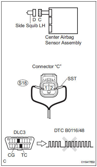
- Turn the ignition switch to the LOCK position.
- Disconnect the negative (-) terminal cable from the battery, and wait for at least 90 seconds.
- Disconnect the connectors from the front seat side airbag assembly LH.
- Connect the black wire side of SST (resistance 2.1 Ω) to the floor wire.
CAUTION: Never connect a tester to the front seat side airbag assembly LH (side squib LH) for measurement, as this may lead to a serious injury due to airbag deployment.
NOTICE: Do not forcibly insert the SST into the terminals of the connector when connecting.
Insert the SST straight into the terminals of the connector.
SST 09843-18060
- Connect the negative (-) terminal cable to the battery, and wait for at least 2 seconds.
- Turn the ignition switch to the ON position, and wait for at least 60 seconds.
- Clear the DTCs stored in memory (5).
- Turn the ignition switch to the LOCK position.
- Turn the ignition switch to the ON position, and wait for at least 60 seconds.
- Check the DTCs
OK: DTC B0116/48 is not output.
HINT: Codes other than DTC B0116/48 may be output at this time, but they are not related to this check.
 Go to step 2

REPLACE FRONT SEAT ASSEMBLY LH
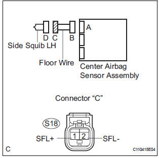
2 CHECK FLOOR WIRE (SIDE SQUIB LH CIRCUIT)
- Turn the ignition switch to the LOCK position.
- Disconnect the negative (-) terminal cable from the battery, and wait for at least 90 seconds.
- Disconnect the SST (resistance 2.1 Ω) from the floor wire.
- Disconnect the connector from the center airbag sensor assembly.
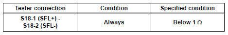
- Measure the resistance according to the value(s) in the table below.
Standard resistance
 REPAIR OR REPLACE FLOOR WIRE

3 CHECK CENTER AIRBAG SENSOR ASSEMBLY
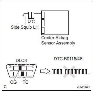
- Connect the connectors to the front seat side airbag assembly LH and the center airbag sensor assembly.
- Connect the negative (-) terminal cable to the battery, and wait for at least 2 seconds.
- Turn the ignition switch to the ON position, and wait for at least 60 seconds.
- Clear the DTCs stored in memory (5).
- Turn the ignition switch to the LOCK position.
- Turn the ignition switch to the ON position, and wait for at least 60 seconds.
- Check the DTCs (5).
OK: DTC B0116/48 is not output.
HINT: Codes other than code B0116/48 may be output at this time, but they are not related to this check.
 REPLACE CENTER AIRBAG SENSOR
ASSEMBLY
REPLACE CENTER AIRBAG SENSOR
ASSEMBLY

USE SIMULATION METHOD TO CHECK
 Short in Side Squib LH Circuit
DTC B0115/47 Short in Side Squib LH Circuit
DESCRIPTION
The side squib LH circuit consists of the center airbag sensor assembly and
the front seat side airbag
assembly LH.
This circuit instruc ...
 Short to GND in Side Squib LH Circuit
DTC B0117/45 Short to GND in Side Squib LH Circuit
DESCRIPTION
The side squib LH circuit consists of the center airbag sensor assembly and
the front seat side airbag
assembly LH.
This circuit ...
Other materials:
Installation
1. INSTALL FRONT PASSENGER AIRBAG ASSEMBLY
Install the front passenger airbag assembly with the
2 screws.
2. INSTALL INSTRUMENT PANEL SUB-ASSEMBLY
3. CONNECT FRONT PASSENGER AIRBAG ASSEMBLY CONNECTOR
Connect the connector to the front passenger airbag
assembly.
...
For rear air conditioning system
ON-VEHICLE INSPECTION
1. INSPECT REAR AIR MIX CONTROL SERVO MOTOR
(a) Inspect servo motor operation.
(1) Connect the positive (+) lead from the battery
to terminal 4 and negative (-) lead to terminal 5,
then check that the arm turns to "HOT" side
smoothly.
(2) Connect the po ...
Installation
1. INSTALL 3 POINT TYPE NO. 2 REAR SEAT BELT ASSEMBLY
Check the degree of tilt when the belt begins to lock
the ELR.
Check that the belt does not lock within 15 of
tilt in all directions but that the belt locks with
over 45 of tilt, when gently moving the
retractor.
If ...
