Toyota Sienna Service Manual: Short in Side Squib LH Circuit
DTC B0115/47 Short in Side Squib LH Circuit
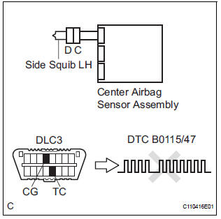
DESCRIPTION
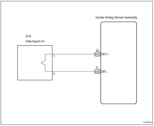
The side squib LH circuit consists of the center airbag sensor assembly and the front seat side airbag assembly LH.
This circuit instructs the SRS to deploy when deployment conditions are met.
DTC B0115/47 is recorded when a short circuit is detected in the side squib LH circuit.
|
DTC No. |
DTC Detecting Condition |
Trouble Area |
| B0115/47 |
|
|
WIRING DIAGRAM
INSPECTION PROCEDURE
HINT:
- Perform the simulation method by selecting the "check mode" (signal check) with the intelligent tester
- After selecting the "check mode" (signal check), perform the simulation method by wiggling each connector of the airbag system or driving the vehicle on a city or rough road
1 CHECK FRONT SEAT SIDE AIRBAG ASSEMBLY LH (SIDE SQUIB LH)
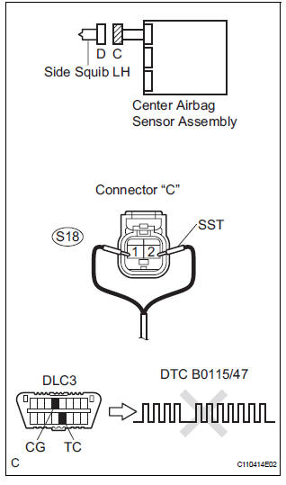
- Turn the ignition switch to the LOCK position.
- Disconnect the negative (-) terminal cable from the battery, and wait for at least 90 seconds.
- Disconnect the connectors from the front seat side airbag assembly LH.
- Connect the black wire side of SST (resistance 2.1 Ω) to the floor wire.
CAUTION: Never connect a tester to the front seat side airbag assembly LH (side squib LH) for measurement, as this may lead to a serious injury due to airbag deployment.
NOTICE: Do not forcibly insert the SST into the terminals of the connector when connecting.
Insert the SST straight into the terminals of the connector.
SST 09843-18060
- Connect the negative (-) terminal cable to the battery, and wait for at least 2 seconds.
- Turn the ignition switch to the ON position, and wait for at least 60 seconds.
- Clear the DTCs stored in memory (5).
- Turn the ignition switch to the LOCK position.
- Turn the ignition switch to the ON position, and wait for at least 60 seconds.
- Check the DTCs (5).
OK: DTC B0115/47 is not output. HINT: Codes other than DTC B0115/47 may be output at this time, but they are not related to this check.
 Go to step 2

REPLACE FRONT SEAT ASSEMBLY LH
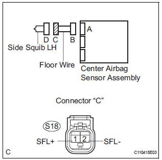
2 CHECK FLOOR WIRE (SIDE SQUIB LH CIRCUIT)
- Turn the ignition switch to the LOCK position.
- Disconnect the negative (-) terminal cable from the battery, and wait for at least 90 seconds.
- Disconnect the SST (resistance 2.1 Ω) from the floor wire.
- Disconnect the connector from the center airbag sensor assembly.
- Release the activation prevention mechanism built into connector "B" (7).
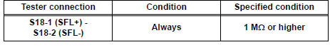
- Measure the resistance according to the value(s) in the table below.
Standard resistance
 REPAIR OR REPLACE FLOOR WIRE

3 CHECK CENTER AIRBAG SENSOR ASSEMBLY
- Connect the connectors to the front seat side airbag assembly LH and the center airbag sensor assembly.
- Connect the negative (-) terminal cable to the battery, and wait for at least 2 seconds.
- Turn the ignition switch to the ON position, and wait for at least 60 seconds.
- Clear the DTCs stored in memory (5).
- Turn the ignition switch to the LOCK position.
- Turn the ignition switch to the ON position, and wait for at least 60 seconds.
- Check the DTCs (5).
OK: DTC B0115/47 is not output. HINT: Codes other than code B0115/47 may be output at this time, but they are not related to this check.
 REPLACE CENTER AIRBAG SENSOR
ASSEMBLY
REPLACE CENTER AIRBAG SENSOR
ASSEMBLY

USE SIMULATION METHOD TO CHECK
 Short to B+ in Side Squib RH Circuit
DTC B0113/42 Short to B+ in Side Squib RH Circuit
DESCRIPTION
The side squib RH circuit consists of the center airbag sensor assembly and
the front seat side airbag
assembly RH.
This circuit i ...
 Open in Side Squib LH Circuit
DTC B0116/48 Open in Side Squib LH Circuit
DESCRIPTION
The side squib LH circuit consists of the center airbag sensor assembly and
the front seat side assembly
LH.
This circuit instructs the S ...
Other materials:
High beam automatic turning on or off conditions
When all of the following conditions are fulfilled, high beam will be
automatically turned on (after approximately 1 second):
Vehicle speed is above approximately 20 mph (32 km/h).
The area ahead of the vehicle is dark.
There are no oncoming or preceding vehicles with headlights or
tail
...
Inspection
1. INSPECT FRONT SEAT INNER BELT ASSEMBLY RH
Release the seat belt (Buckle switch is ON).
Check the resistance between the terminals.
Standard
If the result is not as specified, replace the inner belt
assembly.
Inspect the buckle switch.
Fasten ...
Window defogger switch
INSPECTION
1. INSPECT WINDOW DEFOGGER SWITCH
Check the defogger switch illuminates.
Standard
If the result is not as specified, replace the switch
assembly or bulb.
Check the defogger timer.
Connect the positive (+) lead from the battery
to terminal 2 and ...
