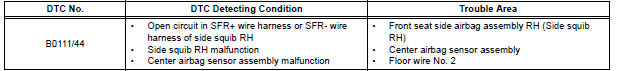
Toyota Sienna Service Manual: Open in Side Squib RH Circuit
DTC B0111/44 Open in Side Squib RH Circuit
DESCRIPTION
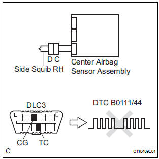
The side squib RH circuit consists of the center airbag sensor assembly and the front seat side airbag assembly RH.
The circuit instructs the SRS to deploy when deployment conditions are met.
DTC B0111/44 is recorded when an open circuit is detected in the side squib RH circuit.
WIRING DIAGRAM
INSPECTION PROCEDURE
HINT:
- Perform the simulation method by selecting the "check mode" (signal check) with the intelligent tester.
- After selecting the "check mode" (signal check), perform the simulation method by wiggling each connector of the airbag system or driving the vehicle on a city or rough road
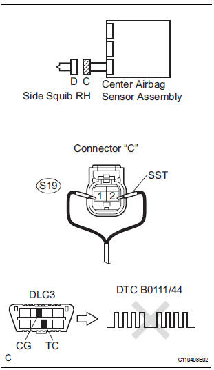
1 CHECK FRONT SEAT SIDE AIRBAG ASSEMBLY RH (SIDE SQUIB RH)
- Turn the ignition switch to the LOCK position.
- Disconnect the negative (-) terminal cable from the battery, and wait for at least 90 seconds.
- Disconnect the connectors from the front seat side airbag assembly RH.
- Connect the black wire side of SST (resistance 2.1 Ω) to the floor wire No. 2.
CAUTION: Never connect a tester to the front seat side airbag assembly RH (side squib RH) for measurement, as this may lead to a serious injury due to airbag deployment.
NOTICE: Do not forcibly insert the SST into the terminals of the connector when connecting.
Insert the SST straight into the terminals of the connector.
SST 09843-18060
- Connect the negative (-) terminal cable to the battery, and wait for at least 2 seconds.
- Turn the ignition switch to the ON position, and wait for at least 60 seconds.
- Clear the DTCs stored in memory.
- Turn the ignition switch to the LOCK position.
- Turn the ignition switch to the ON position, and wait for at least 60 seconds.
- Check the DTCs
OK: DTC B0111/44 is not output.
HINT: Codes other than DTC B0111/44 may be output at this time, but they are not related to this check.
REPLACE FRONT SEAT ASSEMBLY RH
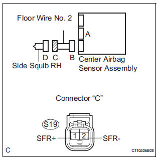
2 CHECK FLOOR WIRE NO.2 (SIDE SQUIB RH CIRCUIT)
- Turn the ignition switch to the LOCK position.
- Disconnect the negative (-) terminal cable from the battery, and wait for at least 90 seconds.
- Disconnect the SST (resistance 2.1 Ω) from the floor wire No. 2.
- Disconnect the connector from the center airbag sensor assembly.
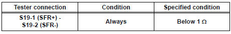
- Measure the resistance according to the value(s) in the table below.
Standard resistance
3 CHECK CENTER AIRBAG SENSOR ASSEMBLY
- Connect the connectors to the front seat side airbag assembly RH and the center airbag sensor assembly.
- Connect the negative (-) terminal cable to the battery, and wait for at least 2 seconds.
- Turn the ignition switch to the ON position, and wait for at least 60 seconds.
- Clear the DTCs stored in memory.
- Turn the ignition switch to the LOCK position.
- Turn the ignition switch to the ON position, and wait for at least 60 seconds.
- Check the DTCs.
OK: DTC B0111/44 is not output.
HINT: Codes other than code B0111/44 may be output at this time, but they are not related to this check.
USE SIMULATION METHOD TO CHECK
 Short in Side Squib RH Circuit
DTC B0110/43 Short in Side Squib RH Circuit
DESCRIPTION
The side squib RH circuit consists of the center airbag sensor assembly and
the front seat side airbag
assembly RH.
The circuit instruct ...
 Short to GND in Side Squib RH Circuit
DTC B0112/41 Short to GND in Side Squib RH Circuit
DESCRIPTION
The side squib RH circuit consists of the center airbag sensor assembly and
the front seat side airbag
assembly RH.
The circuit i ...
Other materials:
Starting the engine
Check that the parking brake is set.
Check that the shift lever is set in P.
Firmly depress the brake pedal.
The engine switch indicator will turn green. If the indicator does not turn
green, the engine cannot be started.
Press the engine switch.
The engine will crank until it sta ...
On-vehicle inspection
1. INSPECT FRONT AIRBAG SENSOR (VEHICLE NOT
INVOLVED IN COLLISION)
Perform a diagnostic system check.
2. INSPECT FRONT AIRBAG SENSOR (VEHICLE
INVOLVED IN COLLISION AND AIRBAG HAS NOT
DEPLOYED)
Perform a diagnostic system check.
When the front bumper of the vehicle o ...
Anti-glare function
Manual anti-glare inside rear view mirror
Reflected light from the headlights of vehicles behind can be reduced
by operating the lever.
Normal position
Anti-glare position
Auto anti-glare inside rear view mirror
Responding to the level of brightness of the headlights of veh ...
