Toyota Sienna Service Manual: Installation
1. INSTALL NO. 2 REAR SEAT OUTER BELT ASSEMBLY
NOTICE: Do not disassemble the retractor.
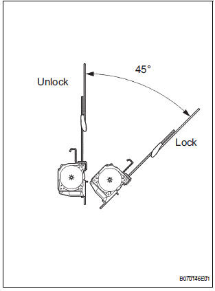
- Check the degree of tilt when the No. 2 rear seat outer belt assembly begins to lock the ELR.
- Check that the belt does not lock within 15 of
tilt in all directions but that the belt locks with
over 45 of tilt, when gently moving the
retractor.
If operation is not as specified, replace the No.
2 rear seat outer belt assembly.
- Install the No. 2 rear seat outer belt assembly
with the bolt on the retractor side.
Torque: Upper bolt 8.5 N*m (87 kgf*cm, 75 in.*lbf)
Lower bolt 42 N*m (430 kgf*cm, 31 ft.*lbf) - Install the No. 2 rear seat outer belt assembly
on the shoulder anchor side with the bolt.
Torque: 42 N*m (430 kgf*cm, 31 ft.*lbf)
2. INSTALL 3 POINT TYPE REAR SEAT BELT ASSEMBLY (for 8-Passenger)
NOTICE: Do not disassemble the retractor.
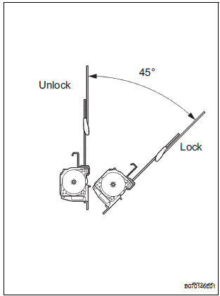
- Check the degree of tilt when the 3 point type rear seat belt assembly begins to lock the ELR.
- Check that the 3 point type rear seat belt
assembly does not lock within 15 of tilt in all
directions but that the 3 point type rear seat belt
assembly locks with over 45 of tilt, when
gently moving the retractor.
If operation is not as specified, replace the 3 point type rear seat belt assembly.
- Install the 3 point type rear seat belt assembly on
the retractor side with the bolt.
Torque: Upper bolt 8.5 N*m (87 kgf*cm, 75 in.*lbf)
Lower bolt 42 N*m (430 kgf*cm, 31 ft.*lbf)
- Install the 3 point type rear seat belt assembly on
the floor anchor side with the bolt.
Torque: 42 N*m (430 kgf*cm, 31 ft.*lbf)
- Check the ELR lock.
NOTICE: The check should be performed with the assembly installed.
- Check that the 3 point type rear seat belt
assembly locks when pulling out the belt
quickly when the 3 point type rear seat belt
assembly is installed.
If operation is not as specified, replace the belt 3 point type rear seat belt assembly.
- Check the fastening function of the child restraint system.
NOTICE: The check should be performed with the assembly installed.
- Check that the belt cannot be pulled out any more but can be rewound after the belt is fully pulled out.
- Check that the belt can be pulled out and
rewound after the belt is fully rewound.
If operation is not as specified, replace the 3 point type rear seat belt assembly.
3. INSTALL NO. 1 REAR SEAT OUTER BELT ASSEMBLY (for 7-Passenger)
HINT: Refer to the instructions for reassembly of the rear No. 1 seat assembly (for captain seat type).
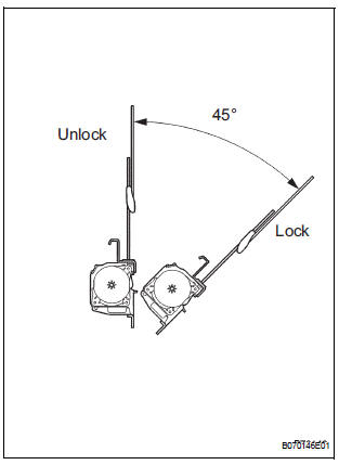
- Check the degree of tilt when the No. 1 rear seat outer belt assembly begins to lock the ELR.
- Check that the belt does not lock within 15 of
tilt in all directions but that the belt locks with
over 45 of tilt, when gently moving the
retractor.
If operation is not as specified, replace the No.
1 rear seat outer belt assembly.
- Install the No. 1 rear seat outer belt assembly with
the bolt and nut.
Torque: 42 N*m (430 kgf*cm, 31 ft.*lbf)
- Install the rear seat shoulder belt cover
- Install the rear seatback board RH
- Install the No. 1 rear seat outer belt assembly with the bolt.
- Check the ELR lock.
NOTICE: The check should be performed with the assembly installed.
- Check that the belt locks when pulling out the
belt quickly when the belt is installed.
If operation is not as specified, replace the No.
1 rear seat outer belt assembly assembly.
- Check the fastening function of the child restraint system.
NOTICE: The check should be performed with the assembly installed.
- Check that the belt cannot be pulled out any more but can be rewound after the belt is fully pulled out.
- Check that the belt can be pulled out and
rewound after the belt is fully rewound.
If operation is not as specified, replace the No.
1 rear seat outer belt assembly.
4. INSTALL REAR WINDOW SIDE GARNISH ASSEMBLY
5. INSTALL FRONT QUARTER TRIM PANEL ASSEMBLY
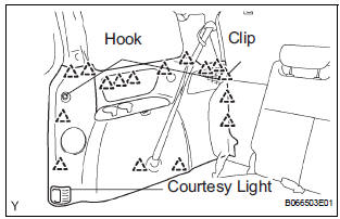
- Engage the 16 clips to install the front quarter trim panel assembly.
- Connect the courtesy light connectors.
- Install the courtesy light.
- Install the 2 package holder net hooks.
- Install the No. 2 rear seat outer belt assembly on the
floor anchor side with the bolt.
Torque: 42 N*m (430 kgf*cm, 31 ft.*lbf)
NOTICE: Do not make the anchor part run onto the protrusion part of the floor panel.
- Install the floor anchor cover.
- Check the ELR lock.
NOTICE: The check should be performed with the assembly installed.
6. INSTALL BACK DOOR SCUFF PLATE
7. INSTALL BACK DOOR WEATHERSTRIP
8. INSTALL REAR DOOR WEATHERSTRIP
9. INSTALL REAR DOOR SCUFF PLATE
 Removal
1. REMOVE REAR DOOR SCUFF PLATE
2. REMOVE REAR DOOR WEATHERSTRIP
3. REMOVE BACK DOOR WEATHERSTRIP
4. REMOVE BACK DOOR SCUFF PLATE
5. REMOVE FRONT QUARTER TRIM PANEL ASSEMBLY
Remove t ...
 Rear center seat inner belt assembly
COMPONENTS
...
Other materials:
Setting up intuitive parking assist
You can change the buzzer sound volume and the screen operating
conditions.
Press the “APPS” button.
Select “Setup” on the screen.
Select “Vehicle” on the screen.
Select “TOYOTA Park Assist Settings” on the screen.
Select the desired item.
The buzzer sound volu ...
Installation
1. INSTALL REAR NO. 2 SEAT ASSEMBLY
Lock the seat leg rear to the floor striker.
Lock the seat leg front to the floor striker.
Install the rear No. 2 seat assembly with the 8 bolts.
Torque: 19 N*m (194 kgf*cm, 14 ft.*lbf)
NOTICE:
Tighten the bolts in the order sho ...
Sound Signal Circuit between Radio Receiver and Stereo Component
Amplifier
DESCRIPTION
The radio receiver sends a sound signal to the stereo component amplifier
through this circuit.
The sound signal that has been sent is amplified by the stereo component
amplifier, and then is sent to
the speakers.
If there is an open or short in the circuit, sound cannot be h ...
