Toyota Sienna Service Manual: Operation check
1. CHECK WINDOW LOCK SWITCH
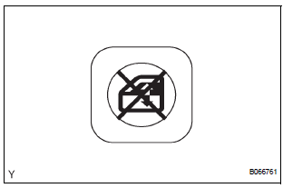
- Check that the passenger side power window and slide door power window operation is disabled when the window lock switch of the power window master switch is pressed.
- Check that the passenger side power window and slide door power windows can be operated when the window lock switch is pressed again.
2. CHECK MANUAL UP/DOWN FUNCTION
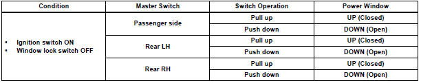
- Check that the driver side power window can be operated using the AUTO (driver side) switch of the power window master switch as follows:
Standard

- Check that the passenger power window and slide door power windows can be operated using each power window regulator switch as follows:
Standard

3. CHECK AUTO UP/DOWN FUNCTION
- Check that the driver side power window can be operated using the AUTO (driver side) switch of the power window master switch as follows:
Standard

4. CHECK REMOTE MANUAL UP/DOWN FUNCTION
- Check that the passenger side power window and slide door power window can be operated using each switch of the power window master switch as follows
Standard
5. CHECK MANUAL DOWN FUNCTION VIA TRANSMITTER
- Check that all power windows and sliding roof (standard type only) operate as follows when operating the transmitter:
Standard
|
Condition |
Transmitter Operation |
Position/Operation |
|
Press UNLOCK switch pressed for 1.5 sec.
or more |
All power windows go DOWN |
|
Press LOCK switch pressed for 1.5 sec. or more | All power windows go UP |
HINT: For a sign for starting operation, the wireless door lock buzzer sounds once (answer-back).
6. CHECK POWER WINDOW OPERATION FUNCTION AFTER IGNITION SWITCH IS TURNED OFF
- When both of the following conditions are fulfilled, check that the power windows can be operated even after the ignition switch is turned off.
- Within 45 seconds after the ignition switch is turned off.
- The front doors are closed.
7. CHECK JAM PROTECTION FUNCTION
HINT: The jam protection function prevents any part of your body from getting caught by accident between the door frame and the door glass during power window operation.
NOTICE: If the power window motor has been reset, raise and lower the door glass several times using MANUAL function before performing the check.
- Check that the door glass goes down by approx. 50 mm (1.97 in.) right when something gets caught between the door frame and door glass during power window operation. However, when the opening between the door frame and the door glass is less than 200 mm (7.87 in.), the door glass keeps going down until the operation reaches 200 mm (7.87 in.) and stops there.
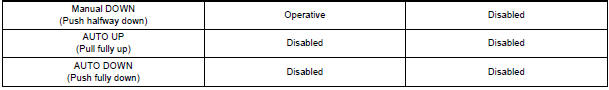
- AUTO UP
- AUTO UP operation after the ignition switch OFF
- MANUAL UP operation after the ignition switch OFF
8. CHECK POWER WINDOW FAIL-SAFE FUNCTION
- If there is a malfunction in the pulse sensor of the power window motor, the power window function will be restricted to partial operation.
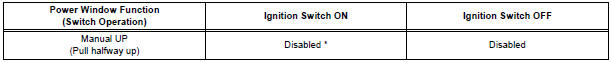
*: However, manual UP function of the power window is operative when fully pulling up the power window switch.
 Power window control system (w/o Jam Protection
Function)
Power window control system (w/o Jam Protection
Function)
PARTS LOCATION
...
 Customize parameters
HINT:
The following items can be customized.
NOTICE:
After confirming whether the items requested by the
customer are applicable or not for customization,
perform customize operations. ...
Other materials:
Installation
1. INSTALL BLOWER ASSEMBLY
(a) Install the blower assembly.
(b) Install the bolt, the 2 screws and the nut.
Torque: Bolt A
9.8 N*m (100 kgf*cm, 87 in.*lbf)
(c) Install the 2 clamps and 2 nuts and wire harness.
2. INSTALL INSTRUMENT PANEL SUB-ASSEMBLY WITH PASSENGER AIRBAG ASSEMBLY
H ...
Airbag ECU Communication Stop
DTC B1281 Airbag ECU Communication Stop
DESCRIPTION
DTC B1281 is output when communication between the airbag ECU and the
multiplex network gateway
ECU stops for more than 10 seconds.
DTC No.
DTC Detection Condition
Trouble Area
B1281
Airbag ECU communi ...
Removal
NOTICE:
When installing, coat the parts indicated by the arrows
with power steering fluid or molybdenum disulfide
lithium base grease (See page PS-21).
1. INSPECT CENTER FRONT WHEEL
2. REMOVE FRONT WHEEL
3. SEPARATE TIE ROD ASSEMBLY LH
SST 09628-62011
4. SEPARATE TIE ROD ASSEMBLY RH
SST 096 ...
